Author Archives: Rich Bibby

About Rich Bibby

Rich is a Senior Network Engineer based in the UK, with a passion for all things Network Automation. Follow me on Twitter and GitHub

CCNP ROUTE Study – OSPF Authentication

authentication

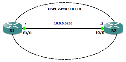
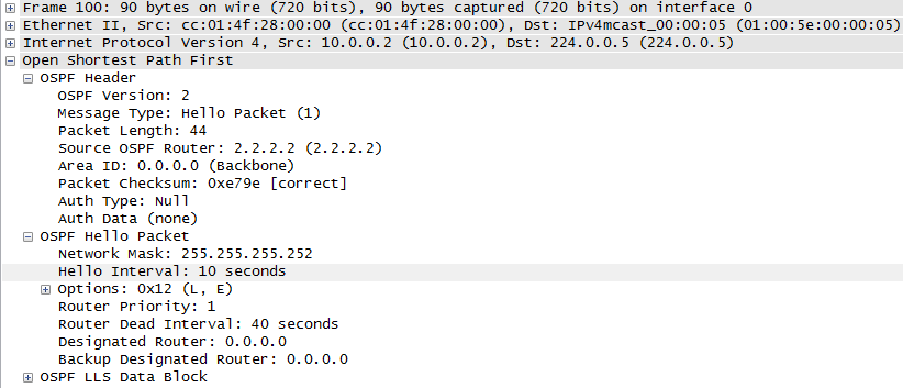
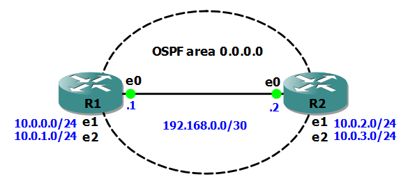
We know that two OSPF routers will become neighbours if they can agree on certain parameters (see my previous post for details) and this is great, but suppose the bad guys were able to connect their own router to the same data link and then cause OSPF routing mayhem – how do we stop this???  

Authentication is the answer, and here’s how we do it.

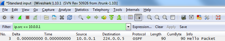
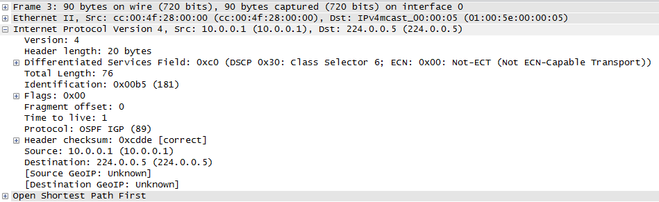
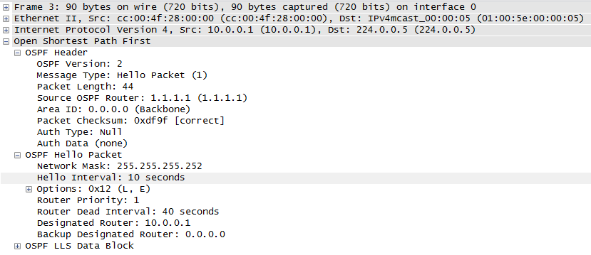
With authentication enabled, every OSPF message sent between routers is authenticated using a pre-shared key. If authentication fails then routers will drop the hello packets, meaning an adjacency cannot form.

Authentication is enabled either per interface or per area, and there are three types of OSPF authentication

  • type 0 – none
  • type 1 – clear text
  • type 2 – MD5

The first example is per interface, type 2 authentication (type 1 is pointless anyway!). Here’s our configuration on R1 (with a matching config on R2):

interface Ethernet0/0
 ip address 10.0.0.1 255.255.255.252
 ip ospf authentication message-digest
 ip ospf message-digest-key 1 md5 CCNPBABY!

To verify this, the show ip ospf interface command will show us that MD5 authentication is enabled and the id of the key being used:

R1#show ip ospf interface
Ethernet0/0 is up, line protocol is up
  Internet Address 10.0.0.1/30, Area 0
  Process ID 1, Router ID 1.1.1.1, Network Type BROADCAST, Cost: 10
  Transmit Delay is 1 sec, State BDR, Priority 1
  Designated Router (ID) 2.2.2.2, Interface address 10.0.0.2
  Backup Designated router (ID) 1.1.1.1, Interface address 10.0.0.1
  Timer intervals configured, Hello 10, Dead 40, Wait 40, Retransmit 5
    oob-resync timeout 40
    Hello due in 00:00:04
  Supports Link-local Signaling (LLS)
  Index 1/1, flood queue length 0
  Next 0x0(0)/0x0(0)
  Last flood scan length is 1, maximum is 1
  Last flood scan time is 0 msec, maximum is 4 msec
  Neighbor Count is 1, Adjacent neighbor count is 1
    Adjacent with neighbor 2.2.2.2  (Designated Router)
  Suppress hello for 0 neighbor(s)
  Message digest authentication enabled
    Youngest key id is 1

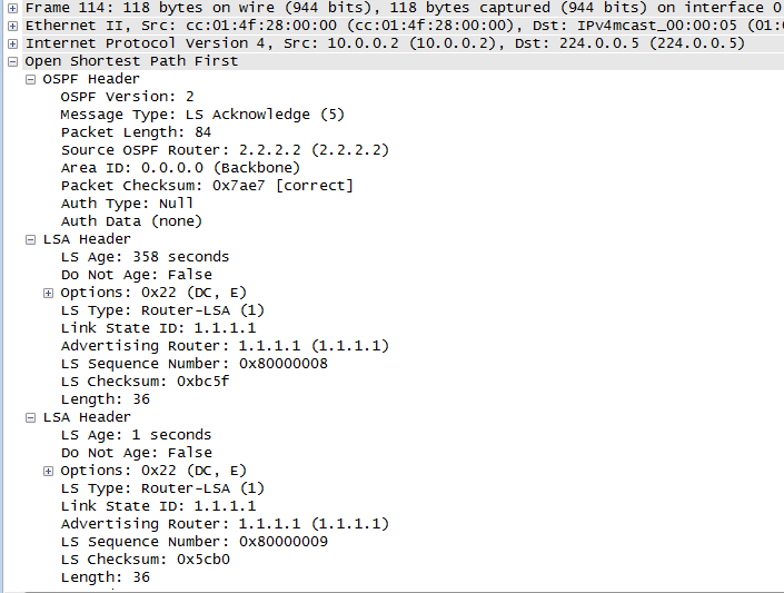
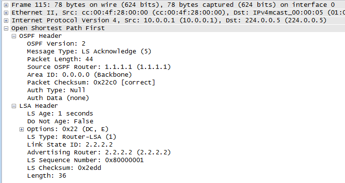
We can also turn on some debugging of ospf packets to verify. The output below shows that type 2 authentication is being used with key id 1:

R1#debug ip ospf packet
OSPF packet debugging is on
R1#
*Mar  1 00:18:00.455: OSPF: rcv. v:2 t:1 l:48 rid:2.2.2.2
      aid:0.0.0.0 chk:0 aut:2 keyid:1 seq:0x3C7EC8A1 from Ethernet0/0

The second example is per area, type 2 authentication. Here’s our configuration on R1 (with a matching config on R2):

!
router ospf 1
 router-id 1.1.1.1
 log-adjacency-changes
 area 0 authentication message-digest
 network 10.0.0.0 0.0.0.3 area 0
!
!
interface Ethernet0/0
 ip address 10.0.0.1 255.255.255.252
 ip ospf message-digest-key 1 md5 CCNPBABY!
 full-duplex

Use the same debugging and show commands as for the per interface config to verify, and you can now sleep a whole lot better at night knowing your OSPF network is secure!

I hope this has been a useful explanation.  Thanks for reading, and good luck with your CCNP studies!

Rich
 
Follow Rich on Twitter

CCNP ROUTE Study – OSPF adjacency set up

In this post we’re going to take a look at the process of two Cisco routers forming an OSPF neighbour adjacency, with an emphasis on what’s going on at a packet level. We’ll look at the packets sent and received on a multi-access network type, in this case Ethernet.

Here’s our network:

OSPF Neighbours

Our OSPF config on R1 looks like this:

router ospf 1
 router-id 1.1.1.1
 log-adjacency-changes
 network 10.0.0.0 0.0.0.3 area 0

As soon as OSPF is enabled, R1 starts to send hello packets out of all interfaces matched by the network statement. These packets are sent to the All OSPF Routers Multicast address 224.0.0.5. Turn on some debugging and we can see this in action:

R1#debug ip ospf hello
OSPF hello events debugging is on
R1#
*Mar  1 06:32:30.270: OSPF: Send hello to 224.0.0.5 area 0 on FastEthernet0/0 from 10.0.0.1
R1#

Now is also good time to take a look at the output from the show ip ospf interface command. This is a great command for troubleshooting OSPF issues. Note some of the highlighted output:

R1#sh ip ospf interface
FastEthernet0/0 is up, line protocol is up
  Internet Address 10.0.0.1/30, Area 0
  Process ID 1, Router ID 1.1.1.1, Network Type BROADCAST, Cost: 1
  Transmit Delay is 1 sec, State DR, Priority 1
  Designated Router (ID) 1.1.1.1, Interface address 10.0.0.1
  No backup designated router on this network
  Timer intervals configured, Hello 10, Dead 40, Wait 40, Retransmit 5
    oob-resync timeout 40
    Hello due in 00:00:03
  Supports Link-local Signaling (LLS)
  Index 1/1, flood queue length 0
  Next 0x0(0)/0x0(0)
  Last flood scan length is 0, maximum is 0
  Last flood scan time is 0 msec, maximum is 0 msec
  Neighbor Count is 0, Adjacent neighbor count is 0
  Suppress hello for 0 neighbor(s)

Now, if we start a packet capture with Wireshark we can take a look at the packets that each router is actually sending out across the wire.

Remember that there are 5 OSPF packet types:

  • type 1 – hello
  • type 2 – database description (DBD)
  • type 3 – link state request (LSR)
  • type 4 – link state update (LSU)
  • type 5 – link state acknowledgement (LSAck)

and 7 neighbour states:

  • state 1 – down
  • state 2 – init
  • state 3 – 2-way
  • state 4 – exstart
  • state 5 – exchange
  • state 6 – loading
  • state 7 – full

Here’s the first packet:

neighbours 0_1

As expected, it’s a type 1 Hello packet from R1. Starting with the IP header we can see that OSPF is IP protocol ID 89, and view the Src and Dst IP addresses:

neighbours 1

Moving on to the OSPF packet we can see the parameters that R1 is advertising to potential neighbours:

neighbours 2

So, at this point R1 is saying “HELLO” to any other devices listening on 224.0.0.5 on the ethernet segment that interface FastEthernet0/0 is connected to and advertising it’s OSPF settings. In order for a neighbour relationship to form, the following must match or be agreed upon by both sides:

  • subnet
  • area number
  • is this a stub area?
  • hello interval
  • dead timer interval
  • authentication (if used)
  • IP MTU

Next, we enable OSPF on R2 and the first thing it does is send out is it’s own type 1 hello packet to see if there are any routers out there able to become neighbours:

neighbours 3

R1 receives R2’s type 1 hello packet, and because both routers agree on the OSPF parameters , R1 places an entry for R2 in it’s neighbour table. At this point the two routers are in the Init state of OSPF.

Next, R1 sends another type 1 hello packet, but this time it is a unicast packet to R2’s IP address instead of a broadcast packet. Also note that in this packet, R1 states it has R2 as an active neighbour:

neighbours 4

At this point the routers are at the two way state. Next on the wire are two packets from R2 to R1. First is a type 2 – database description packet, followed by a type 1 hello packet indicating that R2 also has a neighbour (R1):

neighbours 5

neighbours 6

Now we are at the exstart state. Next comes the exchange state when the routers exchange type 2 – database description packets with each other. During this phase there is a master/slave election, after which the router with the highest router ID becomes the master:

neighbours 7

neighbours 8

neighbours 9

Next, we move onto the loading state, and we can see R2 sending a type 3 – link state request packet to R1, and R1 responding with a type 4 – link state update packet:

neighbours 10

neighbours 11

Our packet capture then shows three more type 4 – link state update packets (1 from R2 and 2 from R1), and these are sent to the All OSPF Routers Multicast address 224.0.0.5:

neighbours 12

neighbours 13

neighbours 14

Finally, we see a type 5 – link state acknowledgement packet from each router, again sent to the All OSPF Routers Multicast address 224.0.0.5:

neighbours 15

neighbours 16

Now that both routers link state databases have been synchronized, we have reached the full state, which we can can confirm with the show ip ospf neighbor command on R1:

R1#show ip ospf neighbor

Neighbor ID     Pri   State           Dead Time   Address         Interface
2.2.2.2           1   FULL/DR        00:00:32    10.0.0.2        FastEthernet0/0

If we also check the show ip ospf interface command on R1 again, we can see it now reports R2 as being it’s neighbour and also that R2 is the designated router (DR):

R1#sh ip os int
FastEthernet0/0 is up, line protocol is up
  Internet Address 10.0.0.1/30, Area 0
  Process ID 1, Router ID 1.1.1.1, Network Type BROADCAST, Cost: 1
  Transmit Delay is 1 sec, State BDR, Priority 1
  Designated Router (ID) 2.2.2.2, Interface address 10.0.0.2
  Backup Designated router (ID) 1.1.1.1, Interface address 10.0.0.1
  Timer intervals configured, Hello 10, Dead 40, Wait 40, Retransmit 5
    oob-resync timeout 40
    Hello due in 00:00:06
  Supports Link-local Signaling (LLS)
  Index 1/1, flood queue length 0
  Next 0x0(0)/0x0(0)
  Last flood scan length is 1, maximum is 2
  Last flood scan time is 0 msec, maximum is 4 msec
  Neighbor Count is 1, Adjacent neighbor count is 1
    Adjacent with neighbor 2.2.2.2  (Designated Router)
  Suppress hello for 0 neighbor(s)

I hope this has been a useful explanation.  Thanks for reading, and good luck with your CCNP studies!

Rich


Follow Rich on Twitter

Junos Basics – Automatic Configuration Archiving

In my previous Junos Basics post I covered configuring a Juniper EX2200C switch as a DHCP server. In this post we’ll step through a really nice feature of Junos that is an absolute no-brainer – configuring your Juniper device to automatically back up a copy of it’s configuration file to an FTP server every time a new candidate configuration is committed. Why would you not enable this!?!?

We have an FTP server with an IP address of 192.168.1.101. The server has an FTP user account called juniper with a password of Jun0S.

Here’s our config:

system {
      archival {
        configuration {
            transfer-on-commit;
            archive-sites {
                "ftp://juniper:Jun0s@192.168.1.101";
                }
            }
      }
}

Now, each time a candidate configuration file is committed, a copy is sent the ftp server automatically.

As you can see this is a really useful feature that is really simple to set up.

I hope this has been a useful explanation.  

Thanks for reading.

Rich

Follow Rich on Twitter

Junos Basics – EX2200C Switch as a DHCP server

In my previous Junos Basics post I covered a simple OSPF configuration in Junos. In this post I’ll step through configuring a Juniper EX2200C switch as a DHCP server.

ex2200c

The EX2200C is a great little switch that’s ideal for a small branch office deployment, and one feature that you might look to take advantage of in such a network is the switch’s ability to function as a DHCP server.

The first step is to enable DHCP for a VLAN (in this case the SALES VLAN 192.168.1.0/24 that we created in a previous post):

set system services dhcp pool 192.168.1.0/24

Next, we’ll set the range of addresses that the server can dish out to clients to 192.168.1.10 – 100:

[edit system services dhcp pool 192.168.1.0/24]
set address-range low 192.168.1.10
set address-range high 192.168.1.100

Then we need to make sure our DHCP clients pick up the correct domain name, DNS server and default gateway IP addresses:

[edit system services dhcp pool 192.168.1.0/24]
set system services dhcp pool 192.168.1.0/24 domain-name small.biz
set system services dhcp pool 192.168.1.0/24 name-server 192.168.1.1
set system services dhcp pool 192.168.1.0/24 router 192.168.1.1 

That’s the basic configuration done so I’ll test it with a client machine connected to the SALES VLAN, and run a couple of show commands to verify our config is working:

To see stats for the client to server DHCP packets:

rich@EX2200C> show system services dhcp statistics
Packets dropped:
    Total                      0

Messages received:
    BOOTREQUEST                0
    DHCPDECLINE                0
    DHCPDISCOVER               1
    DHCPINFORM                 0
    DHCPRELEASE                0
    DHCPREQUEST                2

Messages sent:
    BOOTREPLY                  0
    DHCPOFFER                  1
    DHCPACK                    2
    DHCPNAK                    0

To view the IP address leases:

rich@EX2200C> show system services dhcp binding
IP address       Hardware address   Type     Lease expires at
192.168.1.66     00:26:6c:10:6d:ff  dynamic  2012-06-09 21:59:33 UTC

Finally, sometimes it is useful for a client machine to always receive the same IP address when it requests one from a DHCP server. This is achieved with a DHCP address reservation for the MAC address of the client machine.

To do this we have to go up a level in the configuration, and then set a static binding:

[edit system services dhcp]
set static-binding 00:26:6c:10:6d:ff fixed-address 192.168.1.10

To test this I’ll release/renew the IP address on the client machine, and then check the binding on the server:

rich@EX2200C> show system services dhcp binding
IP address       Hardware address   Type     Lease expires at
192.168.1.10     00:26:6c:10:6d:ff  static   never

I hope this has been a useful explanation.  In my next Junos Basics post I’ll cover automatic configuration archiving to an FTP server.

Thanks for reading.

Rich

Follow Rich on Twitter

Junos Basics – Single Area OSPF

In my previous Junos Basics post I covered a simple VRRP configuration in Junos. In this post I’ll run through a basic OSPF configuration on a pair of Juniper routers.

Here’s our network:

Junos OSPF

Objectives:

  • Establish an OSPF neighbour relationship between R1 and R2
  • increase security by using md5 authentication
  • Configure all router interfaces to be part of OSPF area 0.0.0.0
  • Make interaces e1 and e2 passive for OSPF on each router

First of all, we’ll put the IP addresses onto each interface. Here’s R1’s config:

set interfaces em0 unit 0 family inet address 192.168.0.1/30
set interfaces em1 unit 0 family inet address 10.0.0.1/24
set interfaces em2 unit 0 family inet address 10.0.1.1/24

Here’s R2’s interface configuration and confirmation of IP connectivity to R1:

set interfaces em0 unit 0 family inet address 192.168.0.2/30
set interfaces em1 unit 0 family inet address 10.0.2.1/24
set interfaces em2 unit 0 family inet address 10.0.3.1/24

root> ping 192.168.0.1
PING 192.168.0.1 (192.168.0.1): 56 data bytes
64 bytes from 192.168.0.1: icmp_seq=0 ttl=64 time=0.206 ms
64 bytes from 192.168.0.1: icmp_seq=1 ttl=64 time=0.405 ms

Next, we configure interface em0 on each router to be in OSPF area 0.0.0.0 and to use md5 authentication with a key of “juniper”:

[edit protocols ospf]
root# set area 0.0.0.0 interface em0 authentication md5 1 key juniper

Verify we now have a neighbour relationship formed between R1 and R2:

root@R1> show ospf neighbor
Address          Interface              State     ID               Pri  Dead
192.168.0.2      em0.0                  Full      10.0.2.1         128    37

root@R2> show ospf neighbor
Address          Interface              State     ID               Pri  Dead
192.168.0.1      em0.0                  Full      10.0.0.1         128    30

Next, we’ll configure the other interfaces on each router so that the networks they are attached to are advertised into OSPF area 0.0.0.0, but no neighbour relationships can form over them (passive):

set protocols ospf area 0.0.0.0 interface em1 passive
set protocols ospf area 0.0.0.0 interface em2 passive

If we verify the OSPF interface configuration on R2, we can also see that R2 has won the election process to become the Designated Router (DR) for area 0.0.0.0:

root@R2> show ospf interface
Interface           State   Area            DR ID           BDR ID          Nbrs
em0.0               DR      0.0.0.0         10.0.2.1        10.0.0.1           1
em1.0               DRother 0.0.0.0         0.0.0.0         0.0.0.0            0
em2.0               DRother 0.0.0.0         0.0.0.0         0.0.0.0            0

Next, we’ll take a look at R2’s OSPF routing table and check it contains routes to R1’s attached networks:

root@R2> show ospf route
Topology default Route Table:

Prefix             Path   Route       NH   Metric  NextHop       Nexthop
                   Type   Type        Type         Interface     addr/label
10.0.0.1           Intra  Router      IP        1  em0.0         192.168.0.1
10.0.0.0/24        Intra  Network     IP        2  em0.0         192.168.0.1
10.0.1.0/24        Intra  Network     IP        2  em0.0         192.168.0.1
10.0.2.0/24        Intra  Network     IP        1  em1.0
10.0.3.0/24        Intra  Network     IP        1  em2.0
192.168.0.0/30     Intra  Network     IP        1  em0.0

One other useful verification command displays the OSPF Link State Database:

root@R2> show ospf database

    OSPF database, Area 0.0.0.0
 Type       ID               Adv Rtr           Seq      Age  Opt  Cksum  Len
Router   10.0.0.1         10.0.0.1         0x8000000b   332  0x22 0x2adb  60
Router  *10.0.2.1         10.0.2.1         0x8000000a   325  0x22 0x827b  60
Network *192.168.0.2      10.0.2.1         0x80000003  2514  0x22 0x3476  32

I hope this has been a useful explanation.  In my next Junos Basics post I’ll cover configuring an EX2200C switch as a DHCP server.

Thanks for reading.

Rich

Follow Rich on Twitter

Junos Basics – Virtual Router Redundancy Protocol (VRRP)

In my previous Junos Basics post I covered aggregating ethernet interfaces using LACP on a Juniper switch. In this post I’ll cover a simple VRRP configuration in Junos that provides first hop router redundancy for clients on a local LAN segment.

Here’s our network:

Junos VRRP

Note – all routers are running OSPF, with both interfaces on the Core router, and interface e1 on R1 and e1 on R2 all in OSPF area 0.

Objectives:

  • first hop redundancy for clients on LAN 192.168.1.0/24 out to the core router
  • clients on 192.168.1.0/24 use a default gateway of 192.168.1.3
  • R1 is the master router
  • R1 tracks the IP route to 10.0.0.4/30
  • R1’s priority drops below 100 if there is a loss of the route 10.0.0.4/30 causing R2 to take over forwarding packets for clients on the LAN
  • R1 becomes the master router again if it’s route to 10.0.0.4/30 comes back up

First of all lets just confirm that our OSPF is working and that R1 has learnt the route to 10.0.0.4/30:

root@R1# run show route protocol ospf

inet.0: 6 destinations, 6 routes (6 active, 0 holddown, 0 hidden)
+ = Active Route, - = Last Active, * = Both

10.0.0.4/30        *[OSPF/10] 00:48:20, metric 2
                    > to 10.0.0.1 via em1.0

We’ll start the config on R1, by creating the VRRP group and virtual address on the LAN interface:

[edit interfaces em0 unit 0 family inet address 192.168.1.1/24]

root@R1#
set vrrp-group 10 virtual-address 192.168.1.3

To make sure that R1 is the master router we’ll set it’s priority to 200:

set vrrp-group 10 priority 200

Next, we tell R1 to track the route to 10.0.0.4/30, and to decrease its priority to 99 if the route drops out of R1’s routing table:

set vrrp-group 10 track route 10.0.0.4/30 routing-instance default priority-cost 101

Then we use the preempt command to make sure R1 resumes the master role once the route reappears in the routing table:

set vrrp-group 10 preempt

Now, onto R2. As this router is not the Master, the configuration is very simple – all we need to do is create the VRRP group and set the virtual address on the LAN interface. We don’t even need to set the priority to 100 to make the route tracking mechanism on R1 cause a fail over, as 100 is the default value:

[edit interfaces em0 unit 0 family inet address 192.168.1.2/24]
root@R2# show | display set
set interfaces em0 unit 0 family inet address 192.168.1.2/24 vrrp-group 10 virtual-address 192.168.1.3

That’s it for our simple VRRP config, and now clients on the local LAN have a redundant default gateway to get traffic out to the core router, with automatic fail over from R1 to R2 in the event of R1 losing it’s route to the core.

I hope this has been a useful explanation.  In my next Junos Basics post I’ll cover single area OSPF routing.

Thanks for reading.

Rich

Follow Rich on Twitter

Junos Basics – Aggregated Ethernet Interfaces (LACP)

In my previous Junos Basics post I covered configuring an 802.1Q Trunk between a Juniper EX2200C and a Cisco 2960S. This post will expand upon the previous one by bundling two interfaces together on each switch to form an aggregated link for the trunk.

There are a few proprietary standards for aggregating ethernet links, but Juniper uses the IEEE 802.3ad standard and Cisco can also be configured to use this. The 802.3ad standard is known as Link Aggregation Control Protocol (LACP). LACP can be configured in either Active or Passive mode – in Active mode a switch will always try and form an LACP link with the other side, and in Passive mode a switch will form an LACP link if the other side is in Active mode.

On the Cisco side, the config steps are very simple:

  • specify the interfaces to be aggregated
  • set the protocol to LACP
  • create a Channel Group and specify the LACP mode
  • set the Port Channel interface as a trunk
  • specify which VLAN’s are allowed over the trunk
Cisco2960S(config)#int range gi1/0/47-48
Cisco2960S(config-if-range)#channel-protocol lacp
Cisco2960S(config-if-range)#channel-group 1 mode passive
Cisco2960S(config)#interface po1
Cisco2960S(config-if)#switchport mode trunk
Cisco2960S(config-if)#switchport trunk allowed vlan 100,200

Onto the Juniper side, the first step is to specify the number of aggregated links on the switch:

rich@EX2200C# set chassis aggregated-devices ethernet device-count 1

Next, we have to remove the logical unit configuration from the interfaces that are to be bundled, as logical units are not allowed on aggregated links:

delete interfaces ge-0/1/1 unit 0
delete interfaces ge-0/1/0 unit 0

Next, set the interfaces to use LACP (802.3ad) and to be members of a logical aggregated ethernet port (ports begin with ae):

set interfaces ge-0/1/0 ether-options 802.3ad ae0
set interfaces ge-0/1/1 ether-options 802.3ad ae0

Then we need to set the LACP mode for our new aggregated interface. We’ll make the Juniper side Active, so that it initiates the transmissison of LACP packets:

set interfaces ae0 aggregated-ether-options lacp active

Finally, we need to set the aggregated link to be a trunk, and tell it which VLAN’s to trunk:

set interfaces ae0 unit 0 family ethernet-switching port-mode trunk
set interfaces ae0 unit 0 family ethernet-switching vlan members [SALES IT]

To verify our config, we’ll start on the Cisco side and check the Etherchannel summary:

Cisco2960S#show etherchannel summary
Flags:  D - down        P - bundled in port-channel
        I - stand-alone s - suspended
        H - Hot-standby (LACP only)
        R - Layer3      S - Layer2
        U - in use      f - failed to allocate aggregator

        M - not in use, minimum links not met
        u - unsuitable for bundling
        w - waiting to be aggregated
        d - default port


Number of channel-groups in use: 1
Number of aggregators:           1

Group  Port-channel  Protocol    Ports
------+-------------+-----------+------------------------
1      Po1(SU)         LACP      Gi1/0/47(P) Gi1/0/48(P)

Then we can confirm the trunk config:

Cisco2960S#show interfaces trunk

Port        Mode             Encapsulation  Status        Native vlan
Po1         on               802.1q         trunking      1

Port        Vlans allowed on trunk
Po1         100,200

Port        Vlans allowed and active in management domain
Po1         100,200

Port        Vlans in spanning tree forwarding state and not pruned
Po1         100,200

And on the Juniper side:

rich@EX2200C> show lacp interfaces
Aggregated interface: ae0
    LACP state:       Role   Exp   Def  Dist  Col  Syn  Aggr  Timeout  Activity
      ge-0/1/0       Actor    No    No   Yes  Yes  Yes   Yes     Fast    Active
      ge-0/1/0     Partner    No    No   Yes  Yes  Yes   Yes     Slow   Passive
      ge-0/1/1       Actor    No    No   Yes  Yes  Yes   Yes     Fast    Active
      ge-0/1/1     Partner    No    No   Yes  Yes  Yes   Yes     Slow   Passive
    LACP protocol:        Receive State  Transmit State          Mux State
      ge-0/1/0                  Current   Slow periodic Collecting distributing
      ge-0/1/1                  Current   Slow periodic Collecting distributing

From the above output we can see that our individual interfaces are both Active, with the partner end Passive. For a detailed explanation of the output see this article from Juniper, but suffice to say the Mux State of Collecting and Distributing means the LACP protocol is working correctly.

We can also confirm the trunk is up and trunking for VLAN’s 100 and 200:

rich@EX2200C> show ethernet-switching interfaces
Interface    State  VLAN members        Tag   Tagging  Blocking
ae0.0        up     IT                  200   tagged   unblocked
                    SALES               100   tagged   unblocked

I hope this has been a useful explanation.  In my next Junos Basics post I’ll cover first hop redundancy using VRRP.

Thanks for reading.

Rich

Follow Rich on Twitter

Junos Basics – 802.1Q Trunks

In my previous Junos Basics post I covered creating RVI’s to enable routing between different VLAN’s. In this post I’ll cover configuring an uplink port on an EX2200-C switch to trunk the VLAN’s out to an access layer switch – in this case a Cisco 2960S. This will also allow us to compare the trunk config in Junos Vs Cisco IOS.

Juniper uses the IEEE 802.1Q standard for VLAN trunking, whereas Cisco has it’s own proprietary trunking protocol ISL (Inter Switch Link) as an option on some of it’s switch models. The 2960S range of switches can use only 802.1Q which means both ends of our trunk will talk the same language by default and play together nicely!

Firstly, to configure the port on the Juniper switch as a trunk:

set interfaces ge-0/1/0 unit 0 family ethernet-switching port-mode trunk

This sets the port as a trunk, but it is still not actively trunking for any VLAN’s at this point. We need to specify which VLAN’s should be trunked on the interface:

set interfaces ge-0/1/0 unit 0 family ethernet-switching vlan members [SALES IT]

Moving onto the Cisco side of the trunk, the configuration is equally as simple:

interface GigabitEthernet1/0/47
 switchport trunk allowed vlan 100,200
 switchport mode trunk

The main difference between the two platforms is that as soon as you set the Cisco switch port mode to Trunk, it starts to trunk for ALL VLAN’s, until you tell it which VLAN’s are allowed to be trunked on it. With Juniper it’s almost the reverse in that the port does not trunk for any VLAN’s until you explicitly configure it to do so.

Now both sides of the trunk are configured and connected, we can verify our Juniper config with a couple of show commands:

rich@EX2200C> show interfaces ge-0/1/0.0
  Logical interface ge-0/1/0.0 (Index 79) (SNMP ifIndex 529)
    Flags: SNMP-Traps 0x40004000 Encapsulation: ENET2
    Bandwidth: 0
    Input packets : 0
    Output packets: 4600
    Protocol eth-switch
      Flags: Trunk-Mode
rich@EX2200C> show ethernet-switching interfaces
Interface    State  VLAN members        Tag   Tagging  Blocking
ge-0/0/0.0   down   default                   untagged blocked by STP
ge-0/0/1.0   down   default                   untagged blocked by STP
ge-0/0/2.0   down   default                   untagged blocked by STP
ge-0/0/3.0   down   default                   untagged blocked by STP
ge-0/0/4.0   down   default                   untagged blocked by STP
ge-0/0/5.0   down   default                   untagged blocked by STP
ge-0/0/6.0   down   default                   untagged blocked by STP
ge-0/0/7.0   down   default                   untagged blocked by STP
ge-0/0/8.0   down   default                   untagged blocked by STP
ge-0/0/9.0   down   default                   untagged blocked by STP
ge-0/0/10.0  down   default                   untagged blocked by STP
ge-0/0/11.0  down   default                   untagged blocked by STP
ge-0/1/0.0   up     IT                  200   tagged   unblocked
                    SALES               100   tagged   unblocked
ge-0/1/1.0   down   default                   untagged blocked by STP

Note the VLAN Tags in the above output indicating that both the SALES and IT VLAN’s are being trunked over interface ge-0/1/0.0.

I hope this has been a useful explanation.  In my next Junos Basics post I’ll cover aggregated Ethernet interfaces using the Link Aggregation Control Protocol (LACP).

Thanks for reading.

Rich

Follow Rich on Twitter

CCNP ROUTE Study – EIGRP Route Filtering

There are many reasons why you would want to implement route filtering. A good example would be to prevent routes to transit networks being advertised to a branch router, because no host in the branch would ever need to send packets to a host in the transit network.

Filtering in EIGRP is configured using the distribute-list router subcommand, which can reference either a prefix list, an ACL or a route map to determine whether or not routes should be filtered, and in which direction and (optionally) on which interface.

Here’s our network for this lab:

EIGRP Route Filtering

The three networks attached to router WEST (represented by loopback interfaces) are the ones we will filter routes to, so that they do not appear in router EAST’s routing table. We’ll filter each route in turn using the distribute-list command plus a prefix list, an ACL and a route map.

Without any filtering, each route appears in the routing table of router EAST:

EAST#sh ip route eigrp
     10.0.0.0/24 is subnetted, 3 subnets
D       10.0.2.0 [90/156160] via 192.168.1.1, 00:31:12, FastEthernet0/0
D       10.0.3.0 [90/156160] via 192.168.1.1, 00:31:04, FastEthernet0/0
D       10.0.1.0 [90/156160] via 192.168.1.1, 00:31:21, FastEthernet0/0

Example 1 – filter route to 10.0.1.0/24 using a prefix list:

IP prefix lists examine both the route prefix (subnet number) and the prefix length (subnet mask) for a match. IP prefix lists consist of a command with a sequence number and a permit/deny action. Route prefixes are matched by the command’s prefix/prefix length parameters and prefix lengths are matched by the optional ge (greater than or equal) and le (less than or equal) parameters. If neither ge or le is specified then the prefix length is matched exactly.

In our example we will use a prefix list to exactly match the route to 10.0.1.0/24 and deny it, and then to permit all other routes. First we create the IP prefix list:

ip prefix-list West-PF seq 10 deny 10.0.1.0/24
ip prefix-list West-PF seq 20 permit 0.0.0.0/0 le 32

Command sequence number 10 exactly matches the prefix/prefix length with a deny statement. Sequence 20 uses 0.0.0.0/0 to match all other prefixes and le 32 to match prefix lengths 0-32, which effectively means “match all other routes” and permit them.

We then configure EIGRP with a distribute-list command that references the prefix list and is applied outbound:

WEST#sh run | begin router
router eigrp 10
 network 10.0.0.0
 network 192.168.1.0 0.0.0.3
 distribute-list prefix West-PF out
 no auto-summary

To verify, the show ip protocols command is useful here:

WEST#show ip protocols
Routing Protocol is "eigrp 10"
  Outgoing update filter list for all interfaces is (prefix-list) West-PF

If we now check EAST’s routing table we will see that the route to the 10.0.1.0/24 network has been filtered by router WEST and no longer appears in the routing table:

EAST#sh ip route eigrp
     10.0.0.0/24 is subnetted, 2 subnets
D       10.0.2.0 [90/156160] via 192.168.1.1, 00:12:37, FastEthernet0/0
D       10.0.3.0 [90/156160] via 192.168.1.1, 00:12:37, FastEthernet0/0

Example 2 – filter route to 10.0.2.0/24 using an ACL:

ACL’s use statements referencing an IP address and a wild card mask, followed by a permit/deny action. Remember that as with prefix lists you must also have a statement permitting the other networks that you don’t want to filter. So lets configure our ACL to deny 10.0.2.0/24:

access-list 1 deny   10.0.2.0 0.0.0.255
access-list 1 permit any

It’s worth noting at this point that you cannot have multiple distribute-list commands in your router configuration, and if we try to add our new one without removing the previous command, we get the following:

WEST#conf t
Enter configuration commands, one per line.  End with CNTL/Z.
WEST(config)#router eigrp 10
WEST(config-router)#distribute-list 1 out
% Prefix-list filter exists, de-config first

So, after removing our previous distribute-list command we can add our new one that references our ACL:

WEST(config-router)#distribute-list 1 out

EAST’s routing table now confirms that WEST is not advertising the route to 10.0.2.0/24:

EAST#sh ip route eigrp
     10.0.0.0/24 is subnetted, 2 subnets
D       10.0.3.0 [90/156160] via 192.168.1.1, 19:23:34, FastEthernet0/0
D       10.0.1.0 [90/156160] via 192.168.1.1, 00:01:20, FastEthernet0/0

Example 3 – filter route to 10.0.3.0/24 using a Route Map:

Route Maps have many uses and consist of a set of commands that are processed sequentially. For the purposes of filtering routes in EIGRP we can use a route map that references either an ACL or a prefix list when looking for matches on routes to filter. In this example we’ll create a route map that matches the 10.0.3.0/24 route based on a simple ACL.

First we create the ACL with a single permit statement to match our route:

access-list 2 permit 10.0.3.0 0.0.0.255

Then we create our route map (named Filter-10.0.3.0/24, so we know what it does) with a deny statement that will match IP addresses based on access list 2. Note we also have a permit statement that when used without any match statements, means “match all” effectively permitting all other routes:

route-map Filter-10.0.3.0/24 deny 10
 match ip address 2
!
route-map Filter-10.0.3.0/24 permit 20

Finally, we configure EIGRP to use a distribute-list with the route map:

WEST(config-router)#distribute-list route-map Filter-10.0.3.0/24 out

EAST’s routing table now confirms that WEST is not advertising the route to 10.0.3.0/24:

EAST#sh ip route eigrp
     10.0.0.0/24 is subnetted, 2 subnets
D       10.0.2.0 [90/156160] via 192.168.1.1, 19:23:34, FastEthernet0/0
D       10.0.1.0 [90/156160] via 192.168.1.1, 00:01:20, FastEthernet0/0

I hope this has been a useful explanation.  Thanks for reading, and good luck with your CCNP studies!

Rich


Follow Rich on Twitter

Junos Basics – Inter VLAN Routing

In my previous Junos Basics post I covered the configuration steps required to create VLAN’s on a Juniper switch and assign interfaces to them. In this post I’ll step through the config to enable routing between these VLAN’s and also show a couple of verification commands to check it’s working as expected.

Firstly we configure a routed VLAN interface (RVI) for each VLAN, which is the equivalent of an SVI in Ciscoland. Note that we are configuring the unit value (used for logical interface configuration) to be the same as the VLAN tag, although this is optional:

set interfaces vlan unit 100 family inet address 192.168.1.1/24
set interfaces vlan unit 200 family inet address 192.168.2.1/24

Secondly, we link the VLAN’s to the RVI’s. Note that we specify the unit numbers we set in the previous step for each layer 3 interface:

set vlans SALES l3-interface vlan.100
set vlans IT l3-interface vlan.200

For an RVI to be up and the routing table to have a valid route to it’s VLAN there has to be at least one interface in that VLAN connected and up. I’ve connected a couple of hosts to the interfaces we’ve configured so we can see this in action.

First up we can check the status of our L3 interfaces:

rich@EX2200C> show interfaces terse | match vlan
vlan                    up    up
vlan.100                up    up   inet     192.168.1.1/24
vlan.200                up    up   inet     192.168.2.1/24

All good so far, next let’s check the local routing table to see if the routes to our new VLAN’s are in there and are valid (if there are no UP interfaces in a VLAN, then the route will say “reject”):

rich@EX2200C> show route

inet.0: 4 destinations, 4 routes (4 active, 0 holddown, 0 hidden)
+ = Active Route, - = Last Active, * = Both

192.168.1.0/24     *[Direct/0] 00:08:17
                    > via vlan.100
192.168.1.1/32     *[Local/0] 00:36:50
                      Local via vlan.100
192.168.2.0/24     *[Direct/0] 00:00:41
                    > via vlan.200
192.168.2.1/32     *[Local/0] 00:36:50
                      Local via vlan.200

As a final verification, lets ping one of our RVI’s and make sure it’s up:

rich@EX2200C> ping 192.168.1.1
PING 192.168.1.1 (192.168.1.1): 56 data bytes
64 bytes from 192.168.1.1: icmp_seq=0 ttl=64 time=0.356 ms

I hope this has been a useful explanation.  In the next post in this Junos Basics series, I’ll cover trunking the VLAN’s out to an access layer switch.

Thanks for reading.

Rich

Follow Rich on Twitter