Monthly Archives: August 2013

Junos Basics – EX2200C Switch as a DHCP server

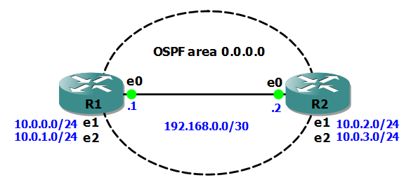
In my previous Junos Basics post I covered a simple OSPF configuration in Junos. In this post I’ll step through configuring a Juniper EX2200C switch as a DHCP server.

ex2200c

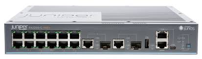
The EX2200C is a great little switch that’s ideal for a small branch office deployment, and one feature that you might look to take advantage of in such a network is the switch’s ability to function as a DHCP server.

The first step is to enable DHCP for a VLAN (in this case the SALES VLAN 192.168.1.0/24 that we created in a previous post):

set system services dhcp pool 192.168.1.0/24

Next, we’ll set the range of addresses that the server can dish out to clients to 192.168.1.10 – 100:

[edit system services dhcp pool 192.168.1.0/24]
set address-range low 192.168.1.10
set address-range high 192.168.1.100

Then we need to make sure our DHCP clients pick up the correct domain name, DNS server and default gateway IP addresses:

[edit system services dhcp pool 192.168.1.0/24]
set system services dhcp pool 192.168.1.0/24 domain-name small.biz
set system services dhcp pool 192.168.1.0/24 name-server 192.168.1.1
set system services dhcp pool 192.168.1.0/24 router 192.168.1.1 

That’s the basic configuration done so I’ll test it with a client machine connected to the SALES VLAN, and run a couple of show commands to verify our config is working:

To see stats for the client to server DHCP packets:

rich@EX2200C> show system services dhcp statistics
Packets dropped:
    Total                      0

Messages received:
    BOOTREQUEST                0
    DHCPDECLINE                0
    DHCPDISCOVER               1
    DHCPINFORM                 0
    DHCPRELEASE                0
    DHCPREQUEST                2

Messages sent:
    BOOTREPLY                  0
    DHCPOFFER                  1
    DHCPACK                    2
    DHCPNAK                    0

To view the IP address leases:

rich@EX2200C> show system services dhcp binding
IP address       Hardware address   Type     Lease expires at
192.168.1.66     00:26:6c:10:6d:ff  dynamic  2012-06-09 21:59:33 UTC

Finally, sometimes it is useful for a client machine to always receive the same IP address when it requests one from a DHCP server. This is achieved with a DHCP address reservation for the MAC address of the client machine.

To do this we have to go up a level in the configuration, and then set a static binding:

[edit system services dhcp]
set static-binding 00:26:6c:10:6d:ff fixed-address 192.168.1.10

To test this I’ll release/renew the IP address on the client machine, and then check the binding on the server:

rich@EX2200C> show system services dhcp binding
IP address       Hardware address   Type     Lease expires at
192.168.1.10     00:26:6c:10:6d:ff  static   never

I hope this has been a useful explanation.  In my next Junos Basics post I’ll cover automatic configuration archiving to an FTP server.

Thanks for reading.

Rich

Follow Rich on Twitter

Junos Basics – Single Area OSPF

In my previous Junos Basics post I covered a simple VRRP configuration in Junos. In this post I’ll run through a basic OSPF configuration on a pair of Juniper routers.

Here’s our network:

Junos OSPF

Objectives:

  • Establish an OSPF neighbour relationship between R1 and R2
  • increase security by using md5 authentication
  • Configure all router interfaces to be part of OSPF area 0.0.0.0
  • Make interaces e1 and e2 passive for OSPF on each router

First of all, we’ll put the IP addresses onto each interface. Here’s R1’s config:

set interfaces em0 unit 0 family inet address 192.168.0.1/30
set interfaces em1 unit 0 family inet address 10.0.0.1/24
set interfaces em2 unit 0 family inet address 10.0.1.1/24

Here’s R2’s interface configuration and confirmation of IP connectivity to R1:

set interfaces em0 unit 0 family inet address 192.168.0.2/30
set interfaces em1 unit 0 family inet address 10.0.2.1/24
set interfaces em2 unit 0 family inet address 10.0.3.1/24

root> ping 192.168.0.1
PING 192.168.0.1 (192.168.0.1): 56 data bytes
64 bytes from 192.168.0.1: icmp_seq=0 ttl=64 time=0.206 ms
64 bytes from 192.168.0.1: icmp_seq=1 ttl=64 time=0.405 ms

Next, we configure interface em0 on each router to be in OSPF area 0.0.0.0 and to use md5 authentication with a key of “juniper”:

[edit protocols ospf]
root# set area 0.0.0.0 interface em0 authentication md5 1 key juniper

Verify we now have a neighbour relationship formed between R1 and R2:

root@R1> show ospf neighbor
Address          Interface              State     ID               Pri  Dead
192.168.0.2      em0.0                  Full      10.0.2.1         128    37

root@R2> show ospf neighbor
Address          Interface              State     ID               Pri  Dead
192.168.0.1      em0.0                  Full      10.0.0.1         128    30

Next, we’ll configure the other interfaces on each router so that the networks they are attached to are advertised into OSPF area 0.0.0.0, but no neighbour relationships can form over them (passive):

set protocols ospf area 0.0.0.0 interface em1 passive
set protocols ospf area 0.0.0.0 interface em2 passive

If we verify the OSPF interface configuration on R2, we can also see that R2 has won the election process to become the Designated Router (DR) for area 0.0.0.0:

root@R2> show ospf interface
Interface           State   Area            DR ID           BDR ID          Nbrs
em0.0               DR      0.0.0.0         10.0.2.1        10.0.0.1           1
em1.0               DRother 0.0.0.0         0.0.0.0         0.0.0.0            0
em2.0               DRother 0.0.0.0         0.0.0.0         0.0.0.0            0

Next, we’ll take a look at R2’s OSPF routing table and check it contains routes to R1’s attached networks:

root@R2> show ospf route
Topology default Route Table:

Prefix             Path   Route       NH   Metric  NextHop       Nexthop
                   Type   Type        Type         Interface     addr/label
10.0.0.1           Intra  Router      IP        1  em0.0         192.168.0.1
10.0.0.0/24        Intra  Network     IP        2  em0.0         192.168.0.1
10.0.1.0/24        Intra  Network     IP        2  em0.0         192.168.0.1
10.0.2.0/24        Intra  Network     IP        1  em1.0
10.0.3.0/24        Intra  Network     IP        1  em2.0
192.168.0.0/30     Intra  Network     IP        1  em0.0

One other useful verification command displays the OSPF Link State Database:

root@R2> show ospf database

    OSPF database, Area 0.0.0.0
 Type       ID               Adv Rtr           Seq      Age  Opt  Cksum  Len
Router   10.0.0.1         10.0.0.1         0x8000000b   332  0x22 0x2adb  60
Router  *10.0.2.1         10.0.2.1         0x8000000a   325  0x22 0x827b  60
Network *192.168.0.2      10.0.2.1         0x80000003  2514  0x22 0x3476  32

I hope this has been a useful explanation.  In my next Junos Basics post I’ll cover configuring an EX2200C switch as a DHCP server.

Thanks for reading.

Rich

Follow Rich on Twitter