


In this post we’re going to take a look at the process of two Cisco routers forming an OSPF neighbour adjacency, with an emphasis on what’s going on at a packet level. We’ll look at the packets sent and received on a multi-access network type, in this case Ethernet.
Here’s our network:
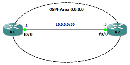
Our OSPF config on R1 looks like this:
router ospf 1
 router-id 1.1.1.1
 log-adjacency-changes
 network 10.0.0.0 0.0.0.3 area 0
As soon as OSPF is enabled, R1 starts to send hello packets out of all interfaces matched by the network statement. These packets are sent to the All OSPF Routers Multicast address 224.0.0.5. Turn on some debugging and we can see this in action:
R1#debug ip ospf hello
OSPF hello events debugging is on
R1#
*Mar  1 06:32:30.270: OSPF: Send hello to 224.0.0.5 area 0 on FastEthernet0/0 from 10.0.0.1
R1#
Now is also good time to take a look at the output from the show ip ospf interface command. This is a great command for troubleshooting OSPF issues. Note some of the highlighted output:
R1#sh ip ospf interface
FastEthernet0/0 is up, line protocol is up
  Internet Address 10.0.0.1/30, Area 0
  Process ID 1, Router ID 1.1.1.1, Network Type BROADCAST, Cost: 1
  Transmit Delay is 1 sec, State DR, Priority 1
  Designated Router (ID) 1.1.1.1, Interface address 10.0.0.1
  No backup designated router on this network
  Timer intervals configured, Hello 10, Dead 40, Wait 40, Retransmit 5
    oob-resync timeout 40
    Hello due in 00:00:03
  Supports Link-local Signaling (LLS)
  Index 1/1, flood queue length 0
  Next 0x0(0)/0x0(0)
  Last flood scan length is 0, maximum is 0
  Last flood scan time is 0 msec, maximum is 0 msec
  Neighbor Count is 0, Adjacent neighbor count is 0
  Suppress hello for 0 neighbor(s)
Now, if we start a packet capture with Wireshark we can take a look at the packets that each router is actually sending out across the wire.
Remember that there are 5 OSPF packet types:
- type 1 – hello
- type 2 – database description (DBD)
- type 3 – link state request (LSR)
- type 4 – link state update (LSU)
- type 5 – link state acknowledgement (LSAck)
and 7 neighbour states:
- state 1 – down
- state 2 – init
- state 3 – 2-way
- state 4 – exstart
- state 5 – exchange
- state 6 – loading
- state 7 – full
Here’s the first packet:
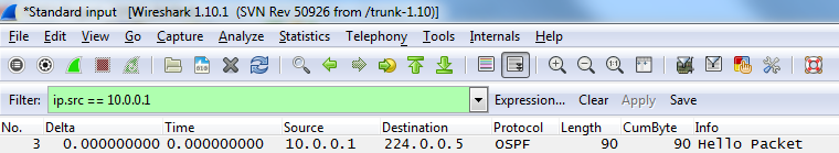
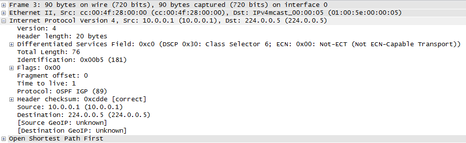
As expected, it’s a type 1 Hello packet from R1. Starting with the IP header we can see that OSPF is IP protocol ID 89, and view the Src and Dst IP addresses:
Moving on to the OSPF packet we can see the parameters that R1 is advertising to potential neighbours:
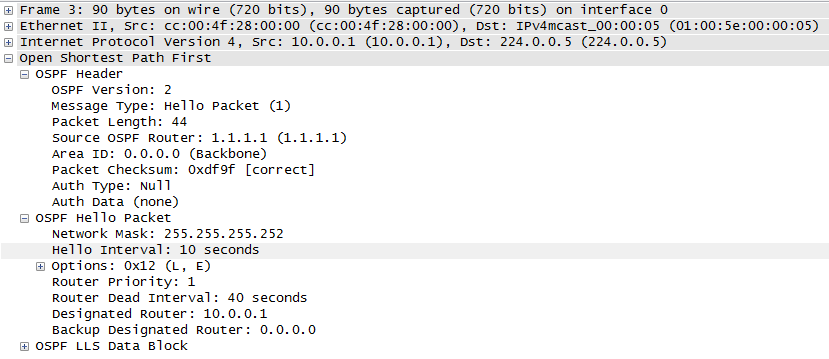
So, at this point R1 is saying “HELLO” to any other devices listening on 224.0.0.5 on the ethernet segment that interface FastEthernet0/0 is connected to and advertising it’s OSPF settings. In order for a neighbour relationship to form, the following must match or be agreed upon by both sides:
- subnet
- area number
- is this a stub area?
- hello interval
- dead timer interval
- authentication (if used)
- IP MTU
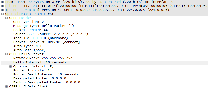
Next, we enable OSPF on R2 and the first thing it does is send out is it’s own type 1 hello packet to see if there are any routers out there able to become neighbours:
R1 receives R2’s type 1 hello packet, and because both routers agree on the OSPF parameters , R1 places an entry for R2 in it’s neighbour table. At this point the two routers are in the Init state of OSPF.
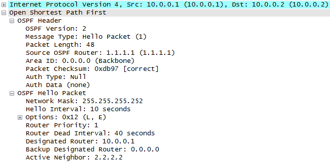
Next, R1 sends another type 1 hello packet, but this time it is a unicast packet to R2’s IP address instead of a broadcast packet. Also note that in this packet, R1 states it has R2 as an active neighbour:
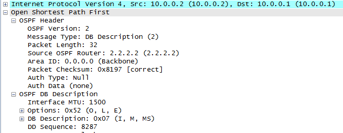
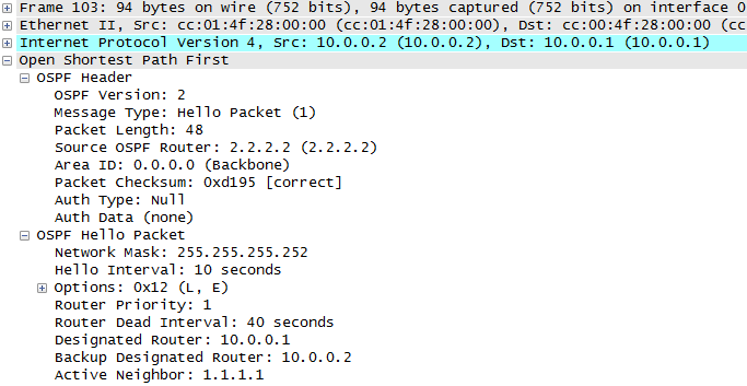
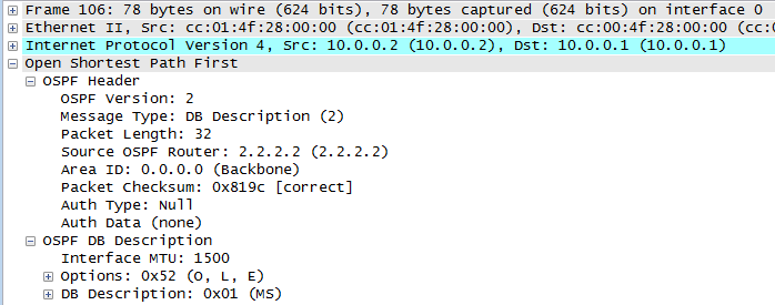
At this point the routers are at the two way state. Next on the wire are two packets from R2 to R1. First is a type 2 – database description packet, followed by a type 1 hello packet indicating that R2 also has a neighbour (R1):
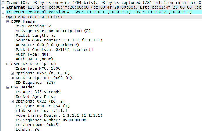
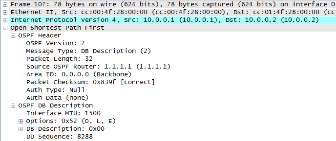
Now we are at the exstart state. Next comes the exchange state when the routers exchange type 2 – database description packets with each other. During this phase there is a master/slave election, after which the router with the highest router ID becomes the master:
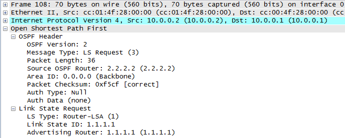
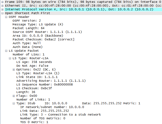
Next, we move onto the loading state, and we can see R2 sending a type 3 – link state request packet to R1, and R1 responding with a type 4 – link state update packet:
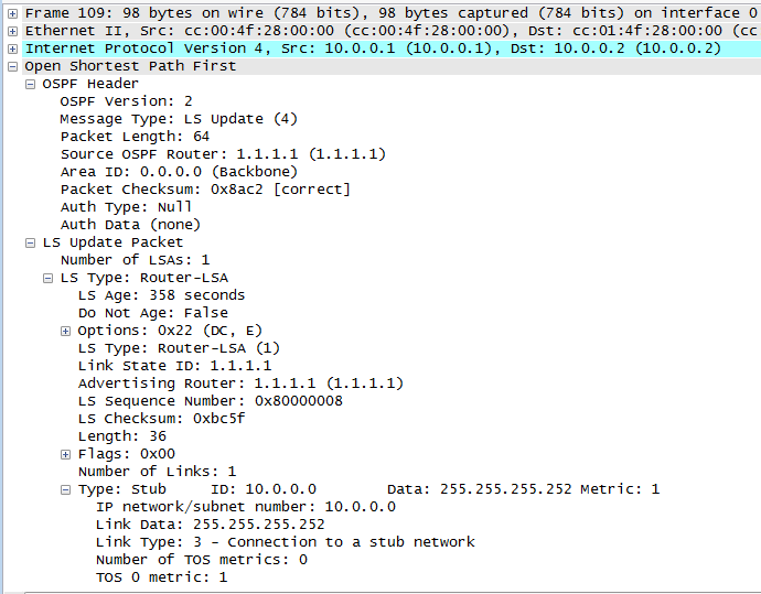
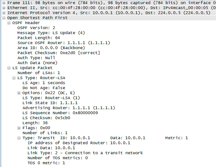
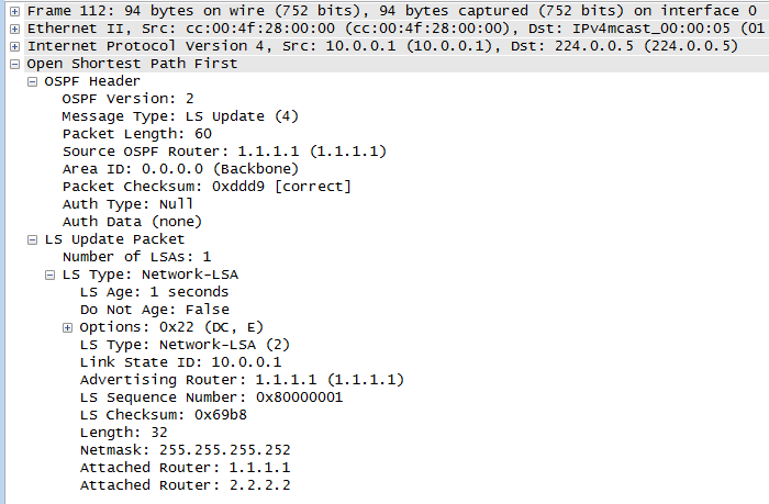
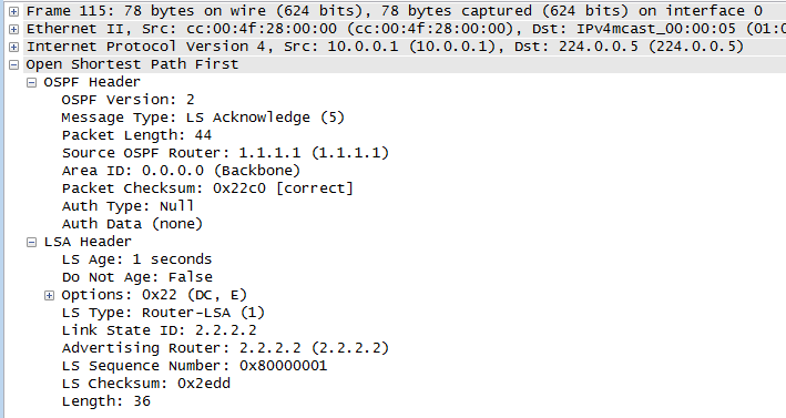
Our packet capture then shows three more type 4 – link state update packets (1 from R2 and 2 from R1), and these are sent to the All OSPF Routers Multicast address 224.0.0.5:
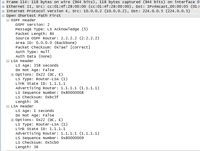
Finally, we see a type 5 – link state acknowledgement packet from each router, again sent to the All OSPF Routers Multicast address 224.0.0.5:
Now that both routers link state databases have been synchronized, we have reached the full state, which we can can confirm with the show ip ospf neighbor command on R1:
R1#show ip ospf neighbor

Neighbor ID     Pri   State           Dead Time   Address         Interface
2.2.2.2           1   FULL/DR        00:00:32    10.0.0.2        FastEthernet0/0
If we also check the show ip ospf interface command on R1 again, we can see it now reports R2 as being it’s neighbour and also that R2 is the designated router (DR):
R1#sh ip os int
FastEthernet0/0 is up, line protocol is up
  Internet Address 10.0.0.1/30, Area 0
  Process ID 1, Router ID 1.1.1.1, Network Type BROADCAST, Cost: 1
  Transmit Delay is 1 sec, State BDR, Priority 1
  Designated Router (ID) 2.2.2.2, Interface address 10.0.0.2
  Backup Designated router (ID) 1.1.1.1, Interface address 10.0.0.1
  Timer intervals configured, Hello 10, Dead 40, Wait 40, Retransmit 5
    oob-resync timeout 40
    Hello due in 00:00:06
  Supports Link-local Signaling (LLS)
  Index 1/1, flood queue length 0
  Next 0x0(0)/0x0(0)
  Last flood scan length is 1, maximum is 2
  Last flood scan time is 0 msec, maximum is 4 msec
  Neighbor Count is 1, Adjacent neighbor count is 1
    Adjacent with neighbor 2.2.2.2  (Designated Router)
  Suppress hello for 0 neighbor(s)
I hope this has been a useful explanation. Thanks for reading, and good luck with your CCNP studies!
Rich
Follow Rich on Twitter
This is an exceptional – among the very best I’ve ever read – explanation of the OSPF adjacency process. You have excellent technical writing skills!
Peace,
John
Hi John,
Wow! thanks for the very kind words. Glad you found it useful 🙂
Rich
It is simply amazing !!!, thank you for sharing such a awsome explanation.
Very good explaination, thanks you so much !