Monthly Archives: June 2013

CCNP ROUTE Study – EIGRP Offset Lists

In certain situations an engineer may need to manipulate EIGRP metrics, and one method is to use Offset Lists to increase both the AD (Advertised Distance) and FD (Feasible Distance) of a route by a certain value – the offset.

Offset List configurations define the following:

  • route(s) that we want to amend the metric for (matching an ACL)
  • direction of the updates being sent or received
  • interface on which updates are sent or received
  • offset integer value
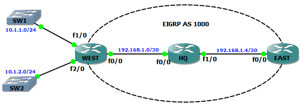
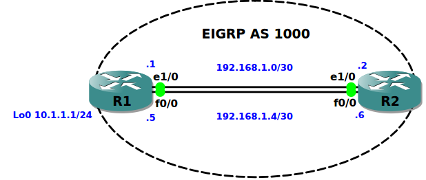
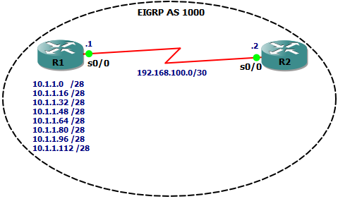
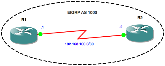
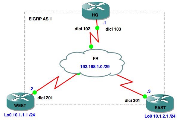
Network diagram:

EIGRP over FR

Objective One:

when router WEST advertises prefix 10.1.1.0 out of interface Serial0/0, it should add 100 to the metric

Lets first check the FD and AD values that HQ has in its topology table for prefix 10.1.1.0/24:

HQ#sh ip eigrp topology 10.1.1.0/24
IP-EIGRP (AS 1): Topology entry for 10.1.1.0/24
  State is Passive, Query origin flag is 1, 1 Successor(s), FD is 2297856
  Routing Descriptor Blocks:
  192.168.1.2 (Serial0/0), from 192.168.1.2, Send flag is 0x0
      Composite metric is (2297856/128256), Route is Internal

Next, we’ll configure the offset list on router WEST:

WEST(config)#access-list 10 permit 10.1.1.0
WEST(config)#router eigrp 1
WEST(config-router)#offset-list 10 out 100 serial 0/0

If we check the FD and AD values on the HQ router again, we’ll see they have both increased by 100:

HQ#sh ip eigrp topology 10.1.1.0/24
IP-EIGRP (AS 1): Topology entry for 10.1.1.0/24
  State is Passive, Query origin flag is 1, 1 Successor(s), FD is 2297856
  Routing Descriptor Blocks:
  192.168.1.2 (Serial0/0), from 192.168.1.2, Send flag is 0x0
      Composite metric is (2297956/128356), Route is Internal

Objective Two:

when HQ router receives an advertisement for prefix 10.1.2.0 in via interface Serial0/0, it should add 100 to the metric

Lets first check the FD and AD values that HQ has in its topology table for prefix 10.1.2.0/24:

HQ#sh ip eigrp topology 10.1.2.0/24
IP-EIGRP (AS 1): Topology entry for 10.1.2.0/24
  State is Passive, Query origin flag is 1, 1 Successor(s), FD is 2297856
  Routing Descriptor Blocks:
  192.168.1.3 (Serial0/0), from 192.168.1.3, Send flag is 0x0
      Composite metric is (2297856/128256), Route is Internal

Next, we’ll configure the offset list on router HQ:

HQ(config)#access-list 10 permit 10.1.2.0  
HQ(config)#router eigrp 1                  
HQ(config-router)#offset-list 10 in 100 serial 0/0

If we check the FD and AD values on the HQ router again, we’ll see they have both increased by 100:

HQ#sh ip eigrp topology 10.1.2.0/24
IP-EIGRP (AS 1): Topology entry for 10.1.2.0/24
  State is Passive, Query origin flag is 1, 1 Successor(s), FD is 2297856
  Routing Descriptor Blocks:
  192.168.1.3 (Serial0/0), from 192.168.1.3, Send flag is 0x0
      Composite metric is (2297956/128356), Route is Internal

I hope this has been a useful explanation.  Thanks for reading, and good luck with your CCNP studies!

Rich


Follow Rich on Twitter

CCNP ROUTE Study – EIGRP Over Frame Relay

There are a couple of gotcha’s when running EIGRP over a WAN technology such as Frame Relay, as opposed to a LAN technology like Ethernet.  To demonstrate one of them let’s consider a typical Frame Relay network operating in a hub and spoke configuration, with our HQ router being the hub and our East and West branch office routers the spokes:

EIGRP over FR

In such a design each router has a single interface (Serial0/0)  connected to the frame relay cloud, and there are PVC’s (permanent virtual circuits) linking HQ to each branch.  This means for example, that when router East sends a packet to router West, the packet traverses East’s PVC to HQ and then back out the other PVC to router West.  So, even though the are two PVC’s configured on the HQ router, they both connect through the same interface.

Here’s all three router’s Frame Relay configurations:

HQ#
!
interface Serial0/0
 ip address 192.168.1.1 255.255.255.248
 encapsulation frame-relay
 serial restart-delay 0
 frame-relay map ip 192.168.1.2 102 broadcast
 frame-relay map ip 192.168.1.3 103 broadcast
 no frame-relay inverse-arp
end
WEST#
!
interface Serial0/0
 ip address 192.168.1.2 255.255.255.248
 encapsulation frame-relay
 serial restart-delay 0
 frame-relay map ip 192.168.1.1 201 broadcast
 frame-relay map ip 192.168.1.3 201
 no frame-relay inverse-arp
end
EAST#
!
interface Serial0/0
 ip address 192.168.1.3 255.255.255.248
 encapsulation frame-relay
 serial restart-delay 0
 frame-relay map ip 192.168.1.1 301 broadcast
 frame-relay map ip 192.168.1.2 301
 no frame-relay inverse-arp
end

We have full IP connectivity between all three routers, which is all well and good, but what happens when we implement a Distance Vector routing protocol (in this case EIGRP) to route between the LAN’s attached to each of our branch routers?  In our lab the local networks are represented by Loopback interface Lo0.

Let’s check the routing tables on each branch router:

WEST#sh ip route

10.0.0.0/24 is subnetted, 1 subnets
C 10.1.1.0 is directly connected, Loopback0
 192.168.1.0/29 is subnetted, 1 subnets
C 192.168.1.0 is directly connected, Serial0/0
EAST#sh ip route

10.0.0.0/24 is subnetted, 1 subnets
C 10.1.2.0 is directly connected, Loopback0
 192.168.1.0/29 is subnetted, 1 subnets
C 192.168.1.0 is directly connected, Serial0/0

In the case of router East, it is directly connected to the 192.168.1.0/29 network, however it cannot see West’s LAN (10.1.1.0/24).  The same is true for router West in that it does not know about East’s LAN (10.1.2.0/24).  The reason for this is Split Horizon.

From Wikipedia:

In computer networking, split-horizon route advertisement is a method of preventing routing loops in distance-vector routing protocols by prohibiting a router from advertising a route back onto the interface from which it was learned.

What this means in our example network is that when the HQ router receives a network advertisement from either the West or East routers telling it about the 10.1.1.0/24 or 10.1.2.0/24 networks respectively, it DOES NOT advertise these routes back out of the same interface on which it learnt them (remember it only has S0/0 connected to the Frame Relay cloud).

Fixing this is easy – we simply disable Split Horizon on the HQ router’s S0/0 interface:

HQ#conf t
Enter configuration commands, one per line. End with CNTL/Z.
HQ(config)#int s0/0
HQ(config-if)#no ip split-horizon eigrp 1

Note that as soon as we do this the HQ router resets the neighbour relationships and sends EIGRP Update packets to the branch routers. We can see this with some debugging enabled:

*Mar  1 00:38:43.671: %DUAL-5-NBRCHANGE: IP-EIGRP(0) 1: Neighbor 192.168.1.2 (Serial0/0) is resync: split horizon changed
*Mar  1 00:44:16.659: EIGRP: Sending UPDATE on Serial0/0 nbr 192.168.1.2
*Mar  1 00:44:16.663:   AS 1, Flags 0xD, Seq 10/0 idbQ 0/0 iidbQ un/rely 0/0 peerQ un/rely 0/1 serno 1-3

Now, if we check the branch routing tables again we will see that they’ve both learned about the  other branches LAN’s:

WEST#sh ip route 

     10.0.0.0/24 is subnetted, 2 subnets
D       10.1.2.0 [90/2809856] via 192.168.1.1, 00:00:08, Serial0/0
C       10.1.1.0 is directly connected, Loopback0
     192.168.1.0/29 is subnetted, 1 subnets
C       192.168.1.0 is directly connected, Serial0/0
EAST#sh ip route

     10.0.0.0/24 is subnetted, 2 subnets
C       10.1.2.0 is directly connected, Loopback0
D       10.1.1.0 [90/2809856] via 192.168.1.1, 00:02:16, Serial0/0
     192.168.1.0/29 is subnetted, 1 subnets
C       192.168.1.0 is directly connected, Serial0/0

Let’s prove we have full connectivity from branch to branch:

WEST#ping 10.1.2.1

Type escape sequence to abort.
Sending 5, 100-byte ICMP Echos to 10.1.2.1, timeout is 2 seconds:
!!!!!
Success rate is 100 percent (5/5)
EAST#ping 10.1.1.1 

Type escape sequence to abort.
Sending 5, 100-byte ICMP Echos to 10.1.1.1, timeout is 2 seconds:
!!!!!
Success rate is 100 percent (5/5)

I hope this has been a useful explanation. Thanks for reading, and good luck with your CCNP studies!

Rich


Follow Rich on Twitter

CCNP ROUTE Study – EIGRP Passive Interfaces

We know that enabling EIGRP on an interface has two effects:

  • EIGRP Hello packets will start being sent out of the interface to multicast  address 224.0.0.10.  This means that neighbour relationships (adjacencies) can be formed with other routers directly connected to the same subnet and using the same EIGRP AS number
  • the network that the interface is part of will be advertised by the EIGRP routing process

If we have a router with interfaces that are not connected to other routers,  then there is no point in it sending Hello packets out of those interfaces.  It is also good security practice to prevent neighbour relationships being formed via interfaces that we know (as the network designer) that no router should ever connect to.

With EIGRP we have the option to make an interface passive, which has two effects on the interface:

  • EIGRP packets are never sent out
  • EIGRP packets received are ignored


Here’s our network for this lab:

EIGRP Passive Interfaces

If we turn on some debugging on router WEST, we can see the default behaviour with Hello packets being sent out of all interfaces that are matched by the EIGRP network statements:

WEST#debug eigrp packets hello
EIGRP Packets debugging is on
 (HELLO)
WEST#
*Mar 1 02:58:47.207: EIGRP: Sending HELLO on FastEthernet2/0
*Mar 1 02:58:47.207: AS 1000, Flags 0x0, Seq 0/0 idbQ 0/0 iidbQ un/rely 0/0
*Mar 1 02:58:47.535: EIGRP: Sending HELLO on FastEthernet1/0
*Mar 1 02:58:47.535: AS 1000, Flags 0x0, Seq 0/0 idbQ 0/0 iidbQ un/rely 0/0
*Mar 1 02:58:48.671: EIGRP: Sending HELLO on FastEthernet0/0
*Mar 1 02:58:48.671: AS 1000, Flags 0x0, Seq 0/0 idbQ 0/0 iidbQ un/rely 0/0


Objective

On router WEST, advertise all connected networks into EIGRP AS 1000, but prevent neighbour relationships being formed over interfaces f1/0 and f2/0.

We have three options up our sleeve to achieve this.  The first two use passive interfaces, and the third uses route redistribution.

Option 1

Configure interfaces f1/0 and f2/0 to be passive:

WEST(config)#router eigrp 1000
WEST(config-router)#passive-interface fastEthernet 1/0
WEST(config-router)#passive-interface fastEthernet 2/0

Option 2

Configure all interfaces to be passive by default, and then explicitly make interface f0/0 active:

WEST(config-router)#passive-interface default

Note that at this point WEST’s neighbour relationship with HQ goes down as EIGRP packets are no longer being sent out of any interfaces:

*Mar 1 00:23:52.867: %DUAL-5-NBRCHANGE: IP-EIGRP(0) 1000: 
Neighbor 192.168.1.2 (FastEthernet0/0) is down: interface passive

Then we make f0/0 active and the neighbour relationship comes back:

WEST(config-router)#no passive-interface fastEthernet 0/0
*Mar 1 00:29:12.587: %DUAL-5-NBRCHANGE: IP-EIGRP(0) 1000: 
Neighbor 192.168.1.2 (FastEthernet0/0) is up: new adjacency


To verify options 1 and 2, we could turn on debugging again and observe Hello packets only being sent out of interface f0/0.  A nicer way is  by using a couple of show commands:

To show all passive interfaces:

WEST#show ip protocols
Routing Protocol is "eigrp 1000"
 Outgoing update filter list for all interfaces is not set
 Incoming update filter list for all interfaces is not set
 Default networks flagged in outgoing updates
 Default networks accepted from incoming updates
 EIGRP metric weight K1=1, K2=0, K3=1, K4=0, K5=0
 EIGRP maximum hopcount 100
 EIGRP maximum metric variance 1
 Redistributing: eigrp 1000
 EIGRP NSF-aware route hold timer is 240s
 Automatic network summarization is not in effect
 Maximum path: 4
 Routing for Networks:
 10.1.1.0/24
 10.1.2.0/24
 192.168.1.0/30
 Passive Interface(s):
 FastEthernet1/0
 FastEthernet2/0
 VoIP-Null0
 Routing Information Sources:
 Gateway Distance Last Update
 Distance: internal 90 external 170

To show only active interfaces:

WEST#show ip eigrp interfaces 
IP-EIGRP interfaces for process 1000
                Xmit Queue  Mean Pacing Time Multicast Pending
Interface Peers Un/Reliable SRTT Un/Reliable Flow Timer Routes
Fa0/0     0     0/0         0    0/1         0          0


Option 3

Instead of using a network statement to advertise the networks connected to f1/0 and f2/0, redistribute these connected networks into EIGRP:

WEST#sh run | s router
router eigrp 1000
 redistribute connected
 network 192.168.1.0 0.0.0.3
 no auto-summary

Although our objective is achieved with all three options, there is a subtle difference with option 3 that we should be aware of.   When directly connected routes are redistributed into EIGRP they are advertised as external routes (admin distance 170) instead of internal routes (admin distance 90), even though they are within the same AS:

EAST#show ip route eigrp
 10.0.0.0/24 is subnetted, 2 subnets
D EX 10.1.2.0 [170/33280] via 192.168.1.5, 00:03:18, FastEthernet0/0
D EX 10.1.1.0 [170/33280] via 192.168.1.5, 00:03:18, FastEthernet0/0
 192.168.1.0/30 is subnetted, 2 subnets
D 192.168.1.0 [90/30720] via 192.168.1.5, 00:37:24, FastEthernet0/0


I hope this has been a useful explanation.  Thanks for reading, and good luck with your CCNP studies!

Rich


Follow Rich on Twitter


CCNP ROUTE Study – EIGRP Unequal-Cost Load Balancing

EIGRP will load balance traffic across up to 16 links (4 by default) of equal cost.  One nice feature of EIGRP is that it can also be configured to load balance across unequal cost links, as opposed to other routing protocols like RIP and OSPF.

Our topology is made up of two routers connected to each other over 10Mbps Ethernet and 100Mbps Fast Ethernet links:

EIGRP LB


The first thing to note here is that even though there is only one router on each side of the link, because we have enabled EIGRP on both interfaces, two neighbour relationships are formed:

R1#sh ip eigrp neighbors 
IP-EIGRP neighbors for process 1000
H Address     Interface Hold  Uptime   SRTT RTO Q   Seq
                        (sec) (ms)              Cnt Num
1 192.168.1.2 Et1/0     10    00:36:21 3    200 0   24
0 192.168.1.6 Fa0/0     11    00:36:21 3    200 0   21

For simplicity I have configured EIGRP to only use the Bandwidth K value when calculating Feasible Distances.  The formula used normally throws up some ridiculous numbers that are of no use when it comes to understanding the protocol, so by telling EIGRP to only use Bandwidth in its calculations, we’ll end up with easier numbers to deal with.

This is achieved by the following commands:

R2(config-router)#router eigrp 1000
R2(config-router)#metric weights 0 1 0 0 0 0

We’ve configured a Loopback interface on R1 with the address 10.1.1.1, and R2 will use the faster link via Fa0/0 to get to this network by default, rather than load balancing traffic across both links.  R2’s routing table confirms this:

R2#sh ip route eigrp
 10.0.0.0/24 is subnetted, 1 subnets
D 10.1.1.0 [90/25600] via 192.168.1.5, 00:00:02, FastEthernet0/0

Also, if we look at R2’s topology table for the EIGRP 1000 routing process, we can see that it knows about both routes to the 10.1.1.0/24 network, but hasn’t placed the slower route in the routing table due to it’s Feasible Distance being 10 times that of the route via fa0/0:

R2#show ip eigrp 1000 topology 
IP-EIGRP Topology Table for AS(1000)/ID(192.168.1.6)
Codes: P - Passive, A - Active, U - Update, Q - Query, R - Reply,
 r - reply Status, s - sia Status
P 10.1.1.0/24, 1 successors, FD is 25600
 via 192.168.1.5 (25600/256), FastEthernet0/0
 via 192.168.1.1 (256000/256), Ethernet1/0

Now let’s configure unequal-cost load balancing to make use of the link via e1/0.  We do this with the variance command:

R2(config)#router eigrp 1000
R2(config-router)#variance 10

By setting the variance to 10 we are telling the router to load balance over routes that have an FD of up to 10 times worse than the FD of the Successor route.  This means that R2 will now place both routes into the routing table:

R2#sh ip route eigrp 
 10.0.0.0/24 is subnetted, 1 subnets
D 10.1.1.0 [90/25600] via 192.168.1.5, 00:10:25, FastEthernet0/0
           [90/256000] via 192.168.1.1, 00:10:25, Ethernet1/0

The result of this is that for every 10 packets that R2 sends to the 10.1.1.0/24 network out of it’s 100Mbps interface it will also send 1 packet out of the 10Mbps interface – load balancing packets across the two unequal-cost links.


I hope this has been a useful explanation.  Thanks for reading.

Rich


Follow Rich on Twitter

CCNP ROUTE Study – EIGRP Route Summarization

In my previous post I covered authentication to improve the security of EIGRP routing.  Next up we are going to look at route summarization.  One feature of EIGRP is that you can summarize pretty much wherever you like, whereas with OSPF for example you are limited to summarizing at area boundaries.  To re-cap, summarization is the process of defining multiple individual networks using a single network/net mask statement.

Why do we do this?  For the purpose of Cisco exams we are talking about reducing the size of routing tables and the number of routing updates required, thereby easing the burden on a routers CPU/memory.  In reality, modern routers are well equipped to handle large routing tables and frequent updates, but we’re trying to pass an exam here, so let’s run with it.

Before we lab this, let me just point out that what we are talking about is manual summarization, which is different from auto summarization.   Auto summary (which is enabled by default) summarizes based on classful network boundaries, and remember from CCNA study that the first thing you do after setting up a routing process is to turn this off as it will generally cause you problems!

Here’s our topology:

EIGRP Route Summarization

R2’s routing table has entries for each of the 10.1.1.x networks attached to R1:

R2#sh ip route eigrp
 10.0.0.0/28 is subnetted, 8 subnets
D 10.1.1.0 [90/2297856] via 192.168.100.1, 2d23h, Serial0/0
D 10.1.1.16 [90/2297856] via 192.168.100.1, 2d23h, Serial0/0
D 10.1.1.32 [90/2297856] via 192.168.100.1, 2d23h, Serial0/0
D 10.1.1.48 [90/2297856] via 192.168.100.1, 2d23h, Serial0/0
D 10.1.1.64 [90/2297856] via 192.168.100.1, 2d23h, Serial0/0
D 10.1.1.80 [90/2297856] via 192.168.100.1, 2d23h, Serial0/0
D 10.1.1.96 [90/2297856] via 192.168.100.1, 2d23h, Serial0/0
D 10.1.1.112 [90/2297856] via 192.168.100.1, 00:00:09, Serial0/0

This isn’t very efficient, so we’ll configure R1 to advertise a summary route to R2 that includes all of the 10.1.1.x networks.  First we need to work out what the net mask for the summary route will be.  We need a mask that will include the address range 10.1.1.0 – 10.1.1.127 and if we change the number of bits used for the net mask to 25 this is exactly what we get (conveniently!) .

How did we work this out?  Well, each network has the same first three octets: 10.1.1.x, therefore we need to manipulate the net mask in the final octet.  Remember our decimal values of the 8 bits are:

128 64 32 16 8 4 2 1

If we set the mask to 255.255.255.0 (/24) we’d have the range 10.1.1.0 – 10.1.1.255, which is too many, but by borrowing the first bit of the final octet (making a /25 mask) we are left with a range of 10.1.1.0 – 10.1.1.127, which is perfect!  Therefore, our summary net mask becomes 255.255.255.128.

This means that R1 should advertise the network 10.1.1.0/25 to R2, and this is configured on the interface that is connected to R2:

R1(config-if)#int se0/0
R1(config-if)#ip summary-address eigrp 1000 10.1.1.0 255.255.255.128

The first thing you’ll notice is the re-sync message indicating that a summary route has been configured on R1

*Mar 4 00:41:26.649: %DUAL-5-NBRCHANGE: IP-EIGRP(0) 1000:
Neighbor 192.168.100.2 (Serial0/0) is resync: summary configured

If we now check the routing table on R2, we’ll see the eight networks attached to R1 summarized under one entry :

R2#show ip route eigrp
 10.0.0.0/25 is subnetted, 1 subnets
D 10.1.1.0 [90/2297856] via 192.168.100.1, 00:10:04, Serial0/0

Just to prove the routing is working let’s ping one of the addresses in the 10.1.1.112 network from R2:

R2#ping 10.1.1.113
Type escape sequence to abort.
Sending 5, 100-byte ICMP Echos to 10.1.1.113, timeout is 2 seconds:
!!!!!
Success rate is 100 percent (5/5), round-trip min/avg/max = 16/24/32 ms


I hope this has been a useful explanation.  Thanks for reading.

Rich


Follow Rich on Twitter

Check Point – Site To Site VPN – Encryption Domain issue

Recently, whilst setting up Site-to-Site VPN with a partner company we saw an issue where the VPN tunnel came up successfully, but the connections allowed by the associated firewall rules failed.

The Check Point tracker logs showed the packets being dropped, and the following information:


encryption failure: According to the policy the packet should not have been decrypted


This is caused by a mis-match in the networks defined in either side’s Encryption Domains.  A quick check revealed that the networks that the partner company was attempting to connect to were missing from the ED on our side of the tunnel.


Follow Rich on Twitter

CCNP ROUTE Study Notes – EIGRP Authentication

So, my CCNP studies slipped onto the back burner recently as I focussed on passing my JNCIA-Junos cert, so it’s time to pick up where my last post left off and move on from a basic EIGRP config to some more advanced stuff.

We know that two EIGRP routers will become neighbours if they have the same AS number, the K values match and they are on the same data link.  This is great, but suppose the bad guys were able to connect their own router to the same data link and then cause EIGRP routing mayhem – how do we stop this???   You guessed it – Authentication, and here’s how we do it:

Here’s our simple topology from last time:


Let’s just verify that all is good and we have happy neighbours:
 

R1#sh ip eigrp nei
IP-EIGRP neighbors for process 1000
H Address       Interface Hold Uptime    SRTT RTO Q Seq
                          (sec) (ms)     Cnt  Num
0 192.168.100.2 Se0/0     10    00:20:48 8    200 0 4


First of all we need to configure a Key Chain on both routers, and we’ll set up keys to be used for June and July.  We’ll allow a slight overlap of when the keys will be accepted from to ensure there is no loss of routing between R1 and R2 should their clocks become out of sync:


R1#sh run | s key
key chain EIGRPAS1000
 key 1
 key-string password1
 accept-lifetime 00:00:00 Jun 1 2013 00:00:00 Jun 30 2013
 send-lifetime 00:00:00 Jun 1 2013 00:00:00 Jun 30 2013
 key 2
 key-string password2
 accept-lifetime 00:00:00 Jun 29 2013 00:00:00 Jul 31 2013
 send-lifetime 00:00:00 Jun 29 2013 00:00:00 Jul 31 2013


Next, we configure R1’s interface to use MD5 hashing of the key (there is no option for plain text), and also to use the Key Chain we created earlier for EIGRP AS 1000 :


R1(config)#interface Serial0/0
R1(config-if)#ip authentication mode eigrp 1000 md5
R1(config-if)#ip authentication key-chain eigrp 1000 EIGRPAS1000

Notice that immediately the adjacency goes down as we haven’t configured the interface on R2 yet:
 

Jun  5 20:40:11.767: %DUAL-5-NBRCHANGE: IP-EIGRP(0) 1000: Neighbor 192.168.100.2
(Serial0/0) is down: authentication mode changed

 
Next, we configure R2’s interface:

R2(config)#interface Serial0/0
R2(config-if)# ip authentication mode eigrp 1000 md5
R2(config-if)# ip authentication key-chain eigrp 1000 EIGRPAS1000

The adjacency comes back up now that both routers are using the same Key Chain to authenticate to each other:
 

Jun  5 20:52:46.091: %DUAL-5-NBRCHANGE: IP-EIGRP(0) 1000: Neighbor 192.168.100.2
(Serial0/0) is up: new adjacency

Next, lets turn on some debugging to verify that authentication is taking place:
 

R1#debug eigrp packets hello
EIGRP Packets debugging is on
 (HELLO)
R1#
Jun  5 20:59:20.771: EIGRP: received packet with MD5 authentication, key id = 1

While we’re at it lets travel forward in time to July and see if Key 2 is being used:
 

Jul  1 21:07:20.927: EIGRP: received packet with MD5 authentication, key id = 2

Job done!  Our EIGRP authentication is working as expected.


Thanks for reading.

Rich


Follow Rich on Twitter