Monthly Archives: July 2013

Junos Basics – Virtual Router Redundancy Protocol (VRRP)

In my previous Junos Basics post I covered aggregating ethernet interfaces using LACP on a Juniper switch. In this post I’ll cover a simple VRRP configuration in Junos that provides first hop router redundancy for clients on a local LAN segment.

Here’s our network:

Junos VRRP

Note – all routers are running OSPF, with both interfaces on the Core router, and interface e1 on R1 and e1 on R2 all in OSPF area 0.

Objectives:

  • first hop redundancy for clients on LAN 192.168.1.0/24 out to the core router
  • clients on 192.168.1.0/24 use a default gateway of 192.168.1.3
  • R1 is the master router
  • R1 tracks the IP route to 10.0.0.4/30
  • R1’s priority drops below 100 if there is a loss of the route 10.0.0.4/30 causing R2 to take over forwarding packets for clients on the LAN
  • R1 becomes the master router again if it’s route to 10.0.0.4/30 comes back up

First of all lets just confirm that our OSPF is working and that R1 has learnt the route to 10.0.0.4/30:

root@R1# run show route protocol ospf

inet.0: 6 destinations, 6 routes (6 active, 0 holddown, 0 hidden)
+ = Active Route, - = Last Active, * = Both

10.0.0.4/30        *[OSPF/10] 00:48:20, metric 2
                    > to 10.0.0.1 via em1.0

We’ll start the config on R1, by creating the VRRP group and virtual address on the LAN interface:

[edit interfaces em0 unit 0 family inet address 192.168.1.1/24]

root@R1#
set vrrp-group 10 virtual-address 192.168.1.3

To make sure that R1 is the master router we’ll set it’s priority to 200:

set vrrp-group 10 priority 200

Next, we tell R1 to track the route to 10.0.0.4/30, and to decrease its priority to 99 if the route drops out of R1’s routing table:

set vrrp-group 10 track route 10.0.0.4/30 routing-instance default priority-cost 101

Then we use the preempt command to make sure R1 resumes the master role once the route reappears in the routing table:

set vrrp-group 10 preempt

Now, onto R2. As this router is not the Master, the configuration is very simple – all we need to do is create the VRRP group and set the virtual address on the LAN interface. We don’t even need to set the priority to 100 to make the route tracking mechanism on R1 cause a fail over, as 100 is the default value:

[edit interfaces em0 unit 0 family inet address 192.168.1.2/24]
root@R2# show | display set
set interfaces em0 unit 0 family inet address 192.168.1.2/24 vrrp-group 10 virtual-address 192.168.1.3

That’s it for our simple VRRP config, and now clients on the local LAN have a redundant default gateway to get traffic out to the core router, with automatic fail over from R1 to R2 in the event of R1 losing it’s route to the core.

I hope this has been a useful explanation.  In my next Junos Basics post I’ll cover single area OSPF routing.

Thanks for reading.

Rich

Follow Rich on Twitter

Junos Basics – Aggregated Ethernet Interfaces (LACP)

In my previous Junos Basics post I covered configuring an 802.1Q Trunk between a Juniper EX2200C and a Cisco 2960S. This post will expand upon the previous one by bundling two interfaces together on each switch to form an aggregated link for the trunk.

There are a few proprietary standards for aggregating ethernet links, but Juniper uses the IEEE 802.3ad standard and Cisco can also be configured to use this. The 802.3ad standard is known as Link Aggregation Control Protocol (LACP). LACP can be configured in either Active or Passive mode – in Active mode a switch will always try and form an LACP link with the other side, and in Passive mode a switch will form an LACP link if the other side is in Active mode.

On the Cisco side, the config steps are very simple:

  • specify the interfaces to be aggregated
  • set the protocol to LACP
  • create a Channel Group and specify the LACP mode
  • set the Port Channel interface as a trunk
  • specify which VLAN’s are allowed over the trunk
Cisco2960S(config)#int range gi1/0/47-48
Cisco2960S(config-if-range)#channel-protocol lacp
Cisco2960S(config-if-range)#channel-group 1 mode passive
Cisco2960S(config)#interface po1
Cisco2960S(config-if)#switchport mode trunk
Cisco2960S(config-if)#switchport trunk allowed vlan 100,200

Onto the Juniper side, the first step is to specify the number of aggregated links on the switch:

rich@EX2200C# set chassis aggregated-devices ethernet device-count 1

Next, we have to remove the logical unit configuration from the interfaces that are to be bundled, as logical units are not allowed on aggregated links:

delete interfaces ge-0/1/1 unit 0
delete interfaces ge-0/1/0 unit 0

Next, set the interfaces to use LACP (802.3ad) and to be members of a logical aggregated ethernet port (ports begin with ae):

set interfaces ge-0/1/0 ether-options 802.3ad ae0
set interfaces ge-0/1/1 ether-options 802.3ad ae0

Then we need to set the LACP mode for our new aggregated interface. We’ll make the Juniper side Active, so that it initiates the transmissison of LACP packets:

set interfaces ae0 aggregated-ether-options lacp active

Finally, we need to set the aggregated link to be a trunk, and tell it which VLAN’s to trunk:

set interfaces ae0 unit 0 family ethernet-switching port-mode trunk
set interfaces ae0 unit 0 family ethernet-switching vlan members [SALES IT]

To verify our config, we’ll start on the Cisco side and check the Etherchannel summary:

Cisco2960S#show etherchannel summary
Flags:  D - down        P - bundled in port-channel
        I - stand-alone s - suspended
        H - Hot-standby (LACP only)
        R - Layer3      S - Layer2
        U - in use      f - failed to allocate aggregator

        M - not in use, minimum links not met
        u - unsuitable for bundling
        w - waiting to be aggregated
        d - default port


Number of channel-groups in use: 1
Number of aggregators:           1

Group  Port-channel  Protocol    Ports
------+-------------+-----------+------------------------
1      Po1(SU)         LACP      Gi1/0/47(P) Gi1/0/48(P)

Then we can confirm the trunk config:

Cisco2960S#show interfaces trunk

Port        Mode             Encapsulation  Status        Native vlan
Po1         on               802.1q         trunking      1

Port        Vlans allowed on trunk
Po1         100,200

Port        Vlans allowed and active in management domain
Po1         100,200

Port        Vlans in spanning tree forwarding state and not pruned
Po1         100,200

And on the Juniper side:

rich@EX2200C> show lacp interfaces
Aggregated interface: ae0
    LACP state:       Role   Exp   Def  Dist  Col  Syn  Aggr  Timeout  Activity
      ge-0/1/0       Actor    No    No   Yes  Yes  Yes   Yes     Fast    Active
      ge-0/1/0     Partner    No    No   Yes  Yes  Yes   Yes     Slow   Passive
      ge-0/1/1       Actor    No    No   Yes  Yes  Yes   Yes     Fast    Active
      ge-0/1/1     Partner    No    No   Yes  Yes  Yes   Yes     Slow   Passive
    LACP protocol:        Receive State  Transmit State          Mux State
      ge-0/1/0                  Current   Slow periodic Collecting distributing
      ge-0/1/1                  Current   Slow periodic Collecting distributing

From the above output we can see that our individual interfaces are both Active, with the partner end Passive. For a detailed explanation of the output see this article from Juniper, but suffice to say the Mux State of Collecting and Distributing means the LACP protocol is working correctly.

We can also confirm the trunk is up and trunking for VLAN’s 100 and 200:

rich@EX2200C> show ethernet-switching interfaces
Interface    State  VLAN members        Tag   Tagging  Blocking
ae0.0        up     IT                  200   tagged   unblocked
                    SALES               100   tagged   unblocked

I hope this has been a useful explanation.  In my next Junos Basics post I’ll cover first hop redundancy using VRRP.

Thanks for reading.

Rich

Follow Rich on Twitter

Junos Basics – 802.1Q Trunks

In my previous Junos Basics post I covered creating RVI’s to enable routing between different VLAN’s. In this post I’ll cover configuring an uplink port on an EX2200-C switch to trunk the VLAN’s out to an access layer switch – in this case a Cisco 2960S. This will also allow us to compare the trunk config in Junos Vs Cisco IOS.

Juniper uses the IEEE 802.1Q standard for VLAN trunking, whereas Cisco has it’s own proprietary trunking protocol ISL (Inter Switch Link) as an option on some of it’s switch models. The 2960S range of switches can use only 802.1Q which means both ends of our trunk will talk the same language by default and play together nicely!

Firstly, to configure the port on the Juniper switch as a trunk:

set interfaces ge-0/1/0 unit 0 family ethernet-switching port-mode trunk

This sets the port as a trunk, but it is still not actively trunking for any VLAN’s at this point. We need to specify which VLAN’s should be trunked on the interface:

set interfaces ge-0/1/0 unit 0 family ethernet-switching vlan members [SALES IT]

Moving onto the Cisco side of the trunk, the configuration is equally as simple:

interface GigabitEthernet1/0/47
 switchport trunk allowed vlan 100,200
 switchport mode trunk

The main difference between the two platforms is that as soon as you set the Cisco switch port mode to Trunk, it starts to trunk for ALL VLAN’s, until you tell it which VLAN’s are allowed to be trunked on it. With Juniper it’s almost the reverse in that the port does not trunk for any VLAN’s until you explicitly configure it to do so.

Now both sides of the trunk are configured and connected, we can verify our Juniper config with a couple of show commands:

rich@EX2200C> show interfaces ge-0/1/0.0
  Logical interface ge-0/1/0.0 (Index 79) (SNMP ifIndex 529)
    Flags: SNMP-Traps 0x40004000 Encapsulation: ENET2
    Bandwidth: 0
    Input packets : 0
    Output packets: 4600
    Protocol eth-switch
      Flags: Trunk-Mode
rich@EX2200C> show ethernet-switching interfaces
Interface    State  VLAN members        Tag   Tagging  Blocking
ge-0/0/0.0   down   default                   untagged blocked by STP
ge-0/0/1.0   down   default                   untagged blocked by STP
ge-0/0/2.0   down   default                   untagged blocked by STP
ge-0/0/3.0   down   default                   untagged blocked by STP
ge-0/0/4.0   down   default                   untagged blocked by STP
ge-0/0/5.0   down   default                   untagged blocked by STP
ge-0/0/6.0   down   default                   untagged blocked by STP
ge-0/0/7.0   down   default                   untagged blocked by STP
ge-0/0/8.0   down   default                   untagged blocked by STP
ge-0/0/9.0   down   default                   untagged blocked by STP
ge-0/0/10.0  down   default                   untagged blocked by STP
ge-0/0/11.0  down   default                   untagged blocked by STP
ge-0/1/0.0   up     IT                  200   tagged   unblocked
                    SALES               100   tagged   unblocked
ge-0/1/1.0   down   default                   untagged blocked by STP

Note the VLAN Tags in the above output indicating that both the SALES and IT VLAN’s are being trunked over interface ge-0/1/0.0.

I hope this has been a useful explanation.  In my next Junos Basics post I’ll cover aggregated Ethernet interfaces using the Link Aggregation Control Protocol (LACP).

Thanks for reading.

Rich

Follow Rich on Twitter

CCNP ROUTE Study – EIGRP Route Filtering

There are many reasons why you would want to implement route filtering. A good example would be to prevent routes to transit networks being advertised to a branch router, because no host in the branch would ever need to send packets to a host in the transit network.

Filtering in EIGRP is configured using the distribute-list router subcommand, which can reference either a prefix list, an ACL or a route map to determine whether or not routes should be filtered, and in which direction and (optionally) on which interface.

Here’s our network for this lab:

EIGRP Route Filtering

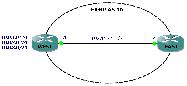
The three networks attached to router WEST (represented by loopback interfaces) are the ones we will filter routes to, so that they do not appear in router EAST’s routing table. We’ll filter each route in turn using the distribute-list command plus a prefix list, an ACL and a route map.

Without any filtering, each route appears in the routing table of router EAST:

EAST#sh ip route eigrp
     10.0.0.0/24 is subnetted, 3 subnets
D       10.0.2.0 [90/156160] via 192.168.1.1, 00:31:12, FastEthernet0/0
D       10.0.3.0 [90/156160] via 192.168.1.1, 00:31:04, FastEthernet0/0
D       10.0.1.0 [90/156160] via 192.168.1.1, 00:31:21, FastEthernet0/0

Example 1 – filter route to 10.0.1.0/24 using a prefix list:

IP prefix lists examine both the route prefix (subnet number) and the prefix length (subnet mask) for a match. IP prefix lists consist of a command with a sequence number and a permit/deny action. Route prefixes are matched by the command’s prefix/prefix length parameters and prefix lengths are matched by the optional ge (greater than or equal) and le (less than or equal) parameters. If neither ge or le is specified then the prefix length is matched exactly.

In our example we will use a prefix list to exactly match the route to 10.0.1.0/24 and deny it, and then to permit all other routes. First we create the IP prefix list:

ip prefix-list West-PF seq 10 deny 10.0.1.0/24
ip prefix-list West-PF seq 20 permit 0.0.0.0/0 le 32

Command sequence number 10 exactly matches the prefix/prefix length with a deny statement. Sequence 20 uses 0.0.0.0/0 to match all other prefixes and le 32 to match prefix lengths 0-32, which effectively means “match all other routes” and permit them.

We then configure EIGRP with a distribute-list command that references the prefix list and is applied outbound:

WEST#sh run | begin router
router eigrp 10
 network 10.0.0.0
 network 192.168.1.0 0.0.0.3
 distribute-list prefix West-PF out
 no auto-summary

To verify, the show ip protocols command is useful here:

WEST#show ip protocols
Routing Protocol is "eigrp 10"
  Outgoing update filter list for all interfaces is (prefix-list) West-PF

If we now check EAST’s routing table we will see that the route to the 10.0.1.0/24 network has been filtered by router WEST and no longer appears in the routing table:

EAST#sh ip route eigrp
     10.0.0.0/24 is subnetted, 2 subnets
D       10.0.2.0 [90/156160] via 192.168.1.1, 00:12:37, FastEthernet0/0
D       10.0.3.0 [90/156160] via 192.168.1.1, 00:12:37, FastEthernet0/0

Example 2 – filter route to 10.0.2.0/24 using an ACL:

ACL’s use statements referencing an IP address and a wild card mask, followed by a permit/deny action. Remember that as with prefix lists you must also have a statement permitting the other networks that you don’t want to filter. So lets configure our ACL to deny 10.0.2.0/24:

access-list 1 deny   10.0.2.0 0.0.0.255
access-list 1 permit any

It’s worth noting at this point that you cannot have multiple distribute-list commands in your router configuration, and if we try to add our new one without removing the previous command, we get the following:

WEST#conf t
Enter configuration commands, one per line.  End with CNTL/Z.
WEST(config)#router eigrp 10
WEST(config-router)#distribute-list 1 out
% Prefix-list filter exists, de-config first

So, after removing our previous distribute-list command we can add our new one that references our ACL:

WEST(config-router)#distribute-list 1 out

EAST’s routing table now confirms that WEST is not advertising the route to 10.0.2.0/24:

EAST#sh ip route eigrp
     10.0.0.0/24 is subnetted, 2 subnets
D       10.0.3.0 [90/156160] via 192.168.1.1, 19:23:34, FastEthernet0/0
D       10.0.1.0 [90/156160] via 192.168.1.1, 00:01:20, FastEthernet0/0

Example 3 – filter route to 10.0.3.0/24 using a Route Map:

Route Maps have many uses and consist of a set of commands that are processed sequentially. For the purposes of filtering routes in EIGRP we can use a route map that references either an ACL or a prefix list when looking for matches on routes to filter. In this example we’ll create a route map that matches the 10.0.3.0/24 route based on a simple ACL.

First we create the ACL with a single permit statement to match our route:

access-list 2 permit 10.0.3.0 0.0.0.255

Then we create our route map (named Filter-10.0.3.0/24, so we know what it does) with a deny statement that will match IP addresses based on access list 2. Note we also have a permit statement that when used without any match statements, means “match all” effectively permitting all other routes:

route-map Filter-10.0.3.0/24 deny 10
 match ip address 2
!
route-map Filter-10.0.3.0/24 permit 20

Finally, we configure EIGRP to use a distribute-list with the route map:

WEST(config-router)#distribute-list route-map Filter-10.0.3.0/24 out

EAST’s routing table now confirms that WEST is not advertising the route to 10.0.3.0/24:

EAST#sh ip route eigrp
     10.0.0.0/24 is subnetted, 2 subnets
D       10.0.2.0 [90/156160] via 192.168.1.1, 19:23:34, FastEthernet0/0
D       10.0.1.0 [90/156160] via 192.168.1.1, 00:01:20, FastEthernet0/0

I hope this has been a useful explanation.  Thanks for reading, and good luck with your CCNP studies!

Rich


Follow Rich on Twitter

Junos Basics – Inter VLAN Routing

In my previous Junos Basics post I covered the configuration steps required to create VLAN’s on a Juniper switch and assign interfaces to them. In this post I’ll step through the config to enable routing between these VLAN’s and also show a couple of verification commands to check it’s working as expected.

Firstly we configure a routed VLAN interface (RVI) for each VLAN, which is the equivalent of an SVI in Ciscoland. Note that we are configuring the unit value (used for logical interface configuration) to be the same as the VLAN tag, although this is optional:

set interfaces vlan unit 100 family inet address 192.168.1.1/24
set interfaces vlan unit 200 family inet address 192.168.2.1/24

Secondly, we link the VLAN’s to the RVI’s. Note that we specify the unit numbers we set in the previous step for each layer 3 interface:

set vlans SALES l3-interface vlan.100
set vlans IT l3-interface vlan.200

For an RVI to be up and the routing table to have a valid route to it’s VLAN there has to be at least one interface in that VLAN connected and up. I’ve connected a couple of hosts to the interfaces we’ve configured so we can see this in action.

First up we can check the status of our L3 interfaces:

rich@EX2200C> show interfaces terse | match vlan
vlan                    up    up
vlan.100                up    up   inet     192.168.1.1/24
vlan.200                up    up   inet     192.168.2.1/24

All good so far, next let’s check the local routing table to see if the routes to our new VLAN’s are in there and are valid (if there are no UP interfaces in a VLAN, then the route will say “reject”):

rich@EX2200C> show route

inet.0: 4 destinations, 4 routes (4 active, 0 holddown, 0 hidden)
+ = Active Route, - = Last Active, * = Both

192.168.1.0/24     *[Direct/0] 00:08:17
                    > via vlan.100
192.168.1.1/32     *[Local/0] 00:36:50
                      Local via vlan.100
192.168.2.0/24     *[Direct/0] 00:00:41
                    > via vlan.200
192.168.2.1/32     *[Local/0] 00:36:50
                      Local via vlan.200

As a final verification, lets ping one of our RVI’s and make sure it’s up:

rich@EX2200C> ping 192.168.1.1
PING 192.168.1.1 (192.168.1.1): 56 data bytes
64 bytes from 192.168.1.1: icmp_seq=0 ttl=64 time=0.356 ms

I hope this has been a useful explanation.  In the next post in this Junos Basics series, I’ll cover trunking the VLAN’s out to an access layer switch.

Thanks for reading.

Rich

Follow Rich on Twitter

Junos Basics – Creating VLAN’s

This is the first in a series of blog posts covering some of the basics of Junos. In this post I’ll be covering the process of creating VLAN’s on a Juniper switch and assigning interfaces to them. The model of switch I am using is an EX2200-C, running Junos 11.4R1.6.

Creating the VLANs’s is very simple. In this example we’ll create 2 VLAN’s, SALES and IT with VLAN ID’s 100 and 200 respectively.

In configuration mode:

set vlans SALES vlan-id 100
set vlans IT vlan-id 200

After committing the configuration we can now view our list of VLAN’s:

rich@EX2200C# show vlans
IT {
    vlan-id 200;
}
SALES {
    vlan-id 100;
}

Next we’ll assign an interface to each VLAN. There are two methods of doing this – you can configure the interface to be a member of a VLAN or you can configure a VLAN to have an interface as a member.

Method 1 – configure the interface:

set interfaces ge-0/0/0 unit 0 family ethernet-switching vlan members SALES

This assigns the interface to the VLAN SALES which can be seen from the interface configuration:

rich@EX2200C> show configuration interfaces ge-0/0/0
unit 0 {
    family ethernet-switching {
        vlan {
            members SALES;
        }
    }
}

Method 2 – Configure the VLAN:

set vlans IT interface ge-0/0/1.0

This method is much quicker and simpler than method 1 and the end result is the same. The difference is that the VLAN membership is not apparent when you view the configuration of the interface:

rich@EX2200C> show configuration interfaces ge-0/0/1
unit 0 {
    family ethernet-switching;
}

Instead, to verify our configuration we need to view the list of VLAN’s again:

rich@EX2200C> show vlans 
Name           Tag     Interfaces
IT             200
                       ge-0/0/1.0
SALES          100
                       ge-0/0/0.0
default
                       ge-0/0/2.0, ge-0/0/3.0, ge-0/0/4.0, ge-0/0/5.0,
                       ge-0/0/6.0, ge-0/0/7.0, ge-0/0/8.0, ge-0/0/9.0,
                       ge-0/0/10.0, ge-0/0/11.0, ge-0/1/0.0, ge-0/1/1.0

Another verification option is the “show ethernet-switching interfaces” command:

rich@EX2200C> show ethernet-switching interfaces
Interface    State  VLAN members        Tag   Tagging  Blocking
ge-0/0/0.0   down   SALES               100   untagged blocked by STP
ge-0/0/1.0   down   IT                  200   untagged blocked by STP
ge-0/0/2.0   down   default                   untagged blocked by STP
ge-0/0/3.0   down   default                   untagged blocked by STP
ge-0/0/4.0   down   default                   untagged blocked by STP
ge-0/0/5.0   down   default                   untagged blocked by STP
.
.

Note also that now we have assigned some interfaces to VLAN’s, all the other interfaces appear as members of the “default” VLAN.

In my next post I’ll cover routing between the VLANS’s we’ve created here.

I hope this has been a useful explanation.  Thanks for reading.

Rich

Follow Rich on Twitter

CCNP ROUTE Study – EIGRP Stub Routers

Stub Routers in EIGRP have two purposes:

  1. to prevent a router from advertising any routes it has learnt via EIGRP to neighbouring routers
  2. to limit the scope of query messages when a route goes “active”

Here’s our network (all links 100Mbps, unless stated):

EIGRP Stub Router

Going “active” means that a Successor route to a network has gone down, and if there is no Feasible Successor (FS) route in a router’s topology table, then the router must send query packets to all it’s neighbours asking if they have a route to the network in question.

In our network, we have decided that there is no point in router WEST advertising routes to networks behind router EAST, as any such routes would be overly long and slow. For the same reason there is no point in our backbone routers querying router WEST if a route to a network behind router EAST goes “active”.

When configuring a Stub Router, we have a few options:

WEST(config-router)#eigrp stub ?
  connected      Do advertise connected routes
  leak-map       Allow dynamic prefixes based on the leak-map
  receive-only   Set IP-EIGRP as receive only neighbor
  redistributed  Do advertise redistributed routes
  static         Do advertise static routes
  summary        Do advertise summary routes

If we just hit Enter, the default is to only advertise directly connected networks and summary routes (either manual or auto). Let’s do that on router WEST:

WEST(config)#router eigrp 1
WEST(config-router)#eigrp stub 

WEST(config-router)#
*Mar  1 01:12:07.847: %DUAL-5-NBRCHANGE: IP-EIGRP(0) 1: Neighbor 192.168.1.1 (Serial0/0) is down: peer info changed
WEST(config-router)#
*Mar  1 01:12:10.563: %DUAL-5-NBRCHANGE: IP-EIGRP(0) 1: Neighbor 192.168.1.1 (Serial0/0) is up: new adjacency

We can verify the config is correct with the show ip eigrp neighbors detail command on one of our backbone routers:

BB1#show ip eigrp neighbors detail
IP-EIGRP neighbors for process 1
H   Address                 Interface       Hold Uptime   SRTT   RTO  Q  Seq
                                            (sec)         (ms)       Cnt Num
0   192.168.1.2             Se0/0             13 00:01:38    2   200  0  20
   Version 12.4/1.2, Retrans: 0, Retries: 0
   Stub Peer Advertising ( CONNECTED SUMMARY ) Routes
   Suppressing queries

As we can see, neighbouring routers now know that router WEST is a Stub router only advertising connected and summary routes, so they will not send it any query messages.

I hope this has been a useful explanation.  Thanks for reading, and good luck with your CCNP studies!

Rich


Follow Rich on Twitter