Author Archives: Rich Bibby

About Rich Bibby

Rich is a Senior Network Engineer based in the UK, with a passion for all things Network Automation. Follow me on Twitter and GitHub

How To – Backup Check Point SPLAT Routing and Interface Information

A quick post showing how to save the routing and interface information from your Check Point Management Servers and Gateways running on the Secure Platform OS.

Simply SSH onto the box and enter

netstat -rn > routes.txt
ifconfig > ifconfig.txt

Copy the 2 txt files off the box and then also grab a copy of /etc/sysconfig/netconf.C and you’re done.

Check Point SecurePlatform CLI reference

To save me time searching for commonly used commands for administering Check Point SecurePlatform (SPLAT) based boxes, I’ve started to put together a list of them here:


General:

chsh -s /bin/bash username – ensures that user “username” is dropped automatically into Expert Mode when logging in through the console

fw ctl pstat (displays data about Capacity, Kernel, INSPECT, connections, NAT and Sync on firewalls)

idle 120 – extends the CLI timeout to 120 seconds when logged into SPshell

unset tmout – disables the CLI timeout when logged into Bash shell or in Expert Mode

cpadmin stop – shuts down the WebUI management services

cpadmin start – starts the WebUI management services

rpm-qa | grep kernel – determine the kernel build


Cluster XL:

cphaprob state (shows the cluster load state)

cphaprob -a if (shows the status of interfaces monitored)

fw ctl pstat – check the output of the Sync section to confirm if sync packets are being sent/received between the cluster members:

Sync:
 Version: new
 Status: Able to Send/Receive sync packets
 Sync packets sent:
 total : 51348080, retransmitted : 7, retrans reqs : 0, acks : 2373
 Sync packets received:
 total : 1026629, were queued : 0, dropped by net : 0
 retrans reqs : 5, received 71 acks
 retrans reqs for illegal seq : 0
 dropped updates as a result of sync overload: 0

Networking:

eth_set eth0 100f (sets the speed and duplex of eth0 to 100Mb Full Duplex – survives a reboot)

ethtool eth0 (displays the settings for interface eth0 such as speed/duplex etc

netstat -rn (to show the routing table of your device)

ifconfig ( to show the list of available interfaces)

tcpdump -i eth0 -s 1500 net 10.200.1.0/24 -w/var/tmp/xxw.pcap

* If you want to filter based on the network address, you should put as above, if filter based on host, change it to ‘host 10.200.1.1’.
**The -s 1500 indicate the normal 1500 size packet you want to capture. If you don’t define 1500, the packets captured will show incomplete details.
***-w is used to save the files to a specific folder. By defining the file extension with .pcap, you’d be able to double click the file to open it via ethereal.

netstat -rn | more (displays the routing table, without resolving names – if you wish to display it per page, use | more at the end of your command line)

netstat -i (displays the Interface Table – useful for displaying error statistics)


Other Useful Linux Commands

gtar -zxvf <file name.tgz> – extracts the contents of a .tgz file to the directory that you are currently in


cat /proc/meminfo or free – Will tell you how much memory is available, how much is used, and how much is swapped, as well asother metrics associated with memory.


grep command can be used at the end of the normal commands to grab specific names you wish to search for. eg. if you wish to see routing table entries for eth3, the command would be:

netstat -rn | grep eth3


df -h displays the amount free disk space no each mounted drive in human readable form ie. GB’s and MB’s.  For example:

[Expert@checkpoint_box]# df -h
Filesystem Size Used Avail Use% Mounted on
/dev/sda6 1004M 160M 793M  17%  /
/dev/sda1 145M  11M  126M  8%   /boot
/dev/sda5 3.4G  3.4G 0     100% /opt
/dev/sda2 1.5G  569M 861M  40%  /sysimg
/dev/sda7 215G  200G 3.9G  99%  /var

How To – Upgrading the software and ASDM images on a Cisco ASA

I recently to needed to upgrade the Software Image on a Cisco ASA 5510 security appliance from version 8.2(2) to 8.2(5).  This process also required upgrading the ASDM software to version 6.4(5) so that the newly upgraded appliance could still be managed via the GUI.


The process for both pieces of the upgrade is very straight forward, so here goes:

Upgrading the ASA image from 8.2(2) to 8.2(5)


Step 1.  Copy the new IOS software image from a TFTP server to the ASA, using the following commands:


ASA5510# copy tftp disk0
Address or name of remote host []? 192.168.10.10
Source filename []? asa825-k8.bin
Destination filename [disk0]? asa825-k8.bin
Accessing tftp://192.168.10.10/asa825-k8.bin;int=Inside_Interface...!!!!!!!!!!!!!
!!!!!!!!!!!!!!!!!!!!!!!!!!!!!!!!!!!!!!!!!!!!!!!!!!!!!!!!!!!!!!!!!!!!!!!!!!!!!!!!!
.
.
Writing file disk0:asa825-k8.bin...
!!!!!!!!!!!!!!!!!!!!!!!!!!!!!!!!!!!!!!!!!!!!!!!!!!!!!!!!!!!!!!!!!!!!!!!!!!!!!!!!!
!!!!!!!!!!!!!!!!!!!!!!!!!!!!!!!!!!!!!!!!!!!!!!!!!!!!!!!!!!!!!!!!!!!!!!!!!!!!!!!!!
15390720 bytes copied in 19.930 secs (810037 bytes/sec)


Step 2.  Verify the new image has been copied to the local disk:


ASA5510# show flash | include asa825-k8.bin


Step 3. Set the ASA to boot from the new image not the old one:


ASA5510# conf t
ASA5510(config)# no boot system disk0:/asa822-k8.bin
ASA5510(config)# boot system disk0:/asa825-k8.bin
ASA5510# write mem
ASA5510# reload


Step 4.  After the reboot, check that the ASA has booted from the new image by issuing the command show version. Verify that the software version and system image file are listed correctly.


Upgrade the ASDM software from version 6.2(5) to 6.4(5):


Step 1.  Copy the new ASDM software image from a TFTP server to the ASA, using the following commands:


ASA5510# copy tftp disk0
Address or name of remote host [] ? 192.168.10.10
Source filename [] ? asdm-645.bin
Destination filename [asdm-645.bin] ? asdm-645.bin


 Step 2.  Verify the new image has been copied to the local disk:


ASA5510# show flash | include asdm-645.bin


Step 3.  Set the ASA to use the new ASDM image:


ASA5510# conf t
ASA5510(config)# asdm image disk0:/asdm-645.bin
ASA5510# write mem


Step 4.  Verify that new ASDM version is working by launching the ASDM and checking the version number is reported 6.4(5), by clicking Help –> About Cisco ASDM 6.4.


Follow Rich on Twitter

How To – Upgrading the license on a Cisco ASA

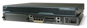
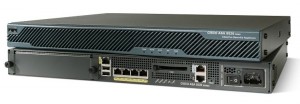
In this short blog post we step through upgrading the license on a Cisco Adaptive Security Appliance (ASA).  The ASA ships with a “Base” license, and we will upgrade to “Security Plus”, which enables advanced features such as Failover.


It’s a very simple process, as follows:


Step 1.  Ensure that the ASA configuration has been backed up


Step 2.  Log onto the ASA via SSH and issue the following commands:


CISCOASA# conf t
CISCOASA(config)# activation-key {activation key as provided by your reseller}


Observe the output after entering the Activation Key:


CISCOASA(config)# activation-key {key string ommitted}
Validating activation key. This may take a few minutes...
Failover is different.
flash activation key: Restricted(R)
new activation key: Unrestricted(UR)
Proceed with update flash activation key? [confirm]
Failover is different.
running activation key: Restricted(R)
new activation key: Unrestricted(UR)
WARNING: The running activation key was not updated with the requested key.
The flash activation key was updated with the requested key, and will
become active after the next reload.
CISCOASA(config)#
CISCOASA(config)# exit
CISCOASA(config)# reload


Step 3.  After the ASA has rebooted, login and issue the command show version | begin Licensed and verify that the license is now reported as Security Plus.  Also check the activation key is reported correctly


Step 4.  erm, there is no step 4.  that’s all there is to it so kick back and relax!


Follow Rich on Twitter

CCNP SWITCH Study Notes – Random Extras

This post is a collection of other random information, config examples etc. that I’ve cobbled together in preparation for the SWITCH exam:

AAA TACACS+ config

enable AAA gloablly on the switch

switch# conf t
switch# (config) aaa new-model

configure the switch with the IP of the TACACS+ server
switch(config)# tacacs-server host 10.10.10.150

configure the encryption used to encrypt traffic between the switch and TACACS+ server
switch(config)# tacacs-server key Str0ngK3y

create an authentication list named “primary” that uses the TACACS+ server  for authentication
switch(config)# aaa authentication login primary group tacacs+

apply the authentication list to the vty connections
switch(config)# line vty 0 4
switch(config)# login authentication primary

Syslog Message types:

There are eight different logging levels.

  • 0—emergencies
  • 1—alerts
  • 2—critical
  • 3—errors
  • 4—warnings
  • 5—notification
  • 6—informational
  • 7—debugging


IP SLA Phases

Control Phase –  establishes time, protocol and port numbers to be used during the probing phase.
  • SLA source sends a control message on UDP port 1967 to the responder
  • Responder opens agreed port and  sends acknowledgement back to the source

Probing Phase – the source device begins sending test packets to the responder for a specified period, and the source device stores the performance statistics in the MIB that can be accessed by SNMP


First Hop Redundancy Protocols

HSRP

  • Cisco proprietary
  • defined by RFC 2281
  • supports authentication
  • only one active router and one standby router, but can do load balancing by using different standby groups
  • uses a virtual IP address that is not the same as one of the actual router IP’s
  • hello packets sent are sent to multicast address 224.0.0.2 on UDP 1985
  • active virtual MAC address is 0000.0c07.acxx – where xx is the group number
  • default timers: Hello Time = 3 sec, Hold Time = 10 Sec
  • by default a standby router will take over if a hello packet is not received for the duration of the Hold Time
  • hello messages are only sent by routers in the Active, Standby or Speak states
  • only routers in the Standby state monitor hello messages from the active router

VRRP

  • standards based
  • supports authentication
  • only one active router, can do load balancing by using standby groups
  • virtual IP address that can be the same as the actual master router’s IP
  • one master and multiple back up routers
  • virtual MAC address is 0000.5e00.01xx – where xx is the group number

GLBP

  • Cisco proprietary
  • supports authentication
  • load balances using multiple routers
  • uses a virtual IP address that is not the same as one of the actual router IP’s
  • a GLBP group can only have one active virtual gateway (AVG’s) but can have multiple active virtual forwarders (AVF’s)
  • AVG is the router with highest priority or if a tie then with highest IP address
  • default load balancing method is per host, round-robin


Port Security

Config example – configure ports fa0/1 and fa0/2 to shut down if more than 2 mac addresses are learnt:

switch#(config) interface range fa0/1-2
switch#(config-if-range)#switchport port-security
switch#(config-if-range)#switchport port-security maximum 2

Violation Actions –

switch#(config-if-range)#switchport port-security violation {restrict | protect | shutdown}

Restrict – discards traffic from illegal host, increments Security Violation counter, send SNMP trap

Protect – discards traffic from illegal host

Shutdown – err-disables the port (default action), generates syslog message


Rapid Spanning Tree (802.1w) Port Roles

  • alternate – failover port for non-designated devices (discarding)
  • backup – redundant link that does not forward packets (discarding)
  • designated – receives frames sent to root (forwarding)
  • root – lowest path cost to root bridge (forwarding)

Default Spanning Tree Timers

  • hello – 2s
  • max age – 20s
  • forward delay – 15s

Etherchannel

LACP – 

  • standards based (802.3d)
  • modes On, Active or PAssive

PAgP – 

  • Cisco proprietary
  • modes On, Auto, Desirable

QoS 802.1D Traffic Types

  • Priority 7 – Network Control
  • Priority 6 –  Interactive Voice
  • Priority 5 – Interactive Video
  • Priority 4 – Controlled Load (Streaming video and multimedia)
  • Priority 3 – Excellent Effort  (loss sensitive, but not time sensitive)
  • Priority 2 – Best effort (typical data traffic)
  • Priority 0 – Background (bulk traffic)


VLAN Trunking Protocol Encapsulation Types

ISL:

  • Cisco
  • encapsulates the entire frame by adding a 30 byte ISL header and trailer
  • max frame size = 1548 bytes (max ethernet frame 1518 + 30 bytes)
802.1Q:
  • IEEE standard
  •  adds a 4 byte header to the orignal ethernet header
  • max frame size = 1522


Voice VLANs

  • disabled by default
  • 802.1X can be configured on a voice VLAN port
  • Spanning Tree Portfast is enabled by default when a port is configured for voice VLAN
  • to properly support Cisco IP phones CDP should be enabled on ports connecting to phones (it is by default)
  • use command switchport voice vlan dot1p to configure a switch port so that voice and data traffic are separated but do not require a unique voice VLAN to be created


Access Control Lists

  • PACL’s – filter inbound traffic on layer 2 ports.  will filter all VLAN traffic on a trunk link if applied to a trunk port
  • RACL’s – filter traffic on a layer 3 interface, cannot be applied to layer 2 traffic
  • VACL’s – filter traffic across a whole VLAN, not individual interfaces


example VACL config – drops traffic matching ACL 10 and forwards all other traffic

create ACL to match interesting traffic:

Switch(config)#ip access-list standard 10
Switch(config-std-nacl)#permit 10.10.10.0 0.0.0.255
Switch(config-std-nacl)#exit

define an access map that uses the ACL above

Switch(config)# vlan access-map Drop10 10
Switch(config-access-map)# match ip address 10
Switch(config-access-map)# action drop
!
Switch(config-access-map)# vlan access-map Drop10 20
Switch(config-access-map)# action forward
!
Switch(config)# vlan filter Drop10 vlan-list 10


Private VLAN’s

Only significant on one switch, and not acknowledged by VTP, so each PVLAN must be configured on every switch that connects them.

  • Primary – can communicate with any secondary VLAN
  • Secondary – can communicate with primary only (Isolated) or with the primary and specific secondary VLANS (community)
  • Promiscuous Port – can communicate with any interface in the PVLAN, connect a gateway device to this type of port
  • Host Port – connect only hosts to these ports

802.1X

enable AAA gloablly on the switch

switch# conf t
switch# (config) aaa new-model

enable 802.1X authentication globally:

switch(config)# dot1x system-auth-control

restore original 802.1X parameters:

switch(config)# dot1x default

enable 802.1X authentication on a single interface:

switch(config)# authentication port-control {auto | force-authorized | force unauthorized}

configure a port to allow traffic from multiple hosts:

switch(config)# authentication host-mode multi-host

Dynamic ARP Inspection

  • prevents man-in-the-middle attacks
  • intercepts, logs and discards ARP packets that have invalid MAC/IP bindings
  • legitimate MAC/IP bindings are stored in a trusted database
  • when DAI is enabled on a switch ports are untrusted by default, and ARP replies sent from untrusted ports are dropped
manually configure trusted ports, such as ports connecting to another switch:
switch(config)# ip arp inspection trust

enable DAI for VLAN’s 10,11,12,13 and 14:

switch(config)# ip arp inspection vlan 10-14


Protecting Spanning Tree

  • Loop Guard – places inconsistent ports in the blocking state.  prevents a switch port from transitioning to a forwarding state when it stops receiving BPDU’s.   A port protected by loop guard will be put in the “loop inconsistent” state if it stops receiving BPDU’s.
  • Root Guard – prevents newly introduced switches being elected the root.  is applied on a per port basis.  ports transition to “root inconsistent” state if it receives a superior BPDU
  • BPDU Guard – disables ports that receive BPDU’s when they shouldn’t.  applied to edge ports that have PortFast enabled


PPDIOO (example steps)

  • Prepare – implementation requirements are determined
  • Plan – current infrastructure is examined
  • Design – detailed implementation plan is created
  • Implement – a pre-defined test plan is implemented
  • Operate – routine maintenance is performed


Cisco Hierarchical Design functions for VLAN’s

  • Access Layer – protocol filtering, basic QoS
  • Distribution Layer – VLAN routing, VLAN Security
  • Core Layer – redundancy for HA, advanced QoS


IP Source Guard

  • designed to prevent DHCP spoofing attacks
  • prevents all IP traffic except for DHCP packets allowed by DHCP snooping or traffic that matches entries in the IP source binding table
  • enable static IP bindings or DHCP snooping before IP source guard can be used, otherwise all traffic will be dropped


SNMP Version 3 features

  • encryption
  • authentication (user names)
  • message integrity
  • requires IOS 12.0 or later


High Availability components

  • Network level – backup switches, redundant links with STP
  • System Level – redundant power supplies, Stack Wise technology
  • Management and Monitoring


CCNP SWITCH Exam – Revision Plan

So…..with my SWITCH exam scheduled for a couple of weeks from now, it’s time to knuckle down for some serious prep work.  This is going to be a mixture of reading, lab exercises and practice questions.  To give this some structure and ensure I cover everything off I thought it would be a good idea to document it so I can tick off each bit as I go along.  Here’s the plan:

Monday 5th March:  

  • read CCNP quick ref guide – chapter 1 – Campus Network Design
  • read SWITCH portable command guide chapter 1 – Analysing Campus Network Designs
  • take Boson Practice exam A and review incorrect answers

Tuesday 6th March:

  • read CCNP quick ref guide – chapter 2 – VLAN Implementation
  • read SWITCH portable command guide chapter 2 – Implementing VLANS in a Campus Network
  • Lab 2-1, Static VLANS, VLAN Trunking, and VTP Domains and Modes
  • Lab 2-2, Configuring EtherChannel

Wednesday 7th March:

  • read CCNP quick ref guide – chapter 3 – Spanning Tree
  • read SWITCH portable command guide chapter 3 – Implementing Spanning Tree
  • Lab 3-1, Spanning Tree Protocol (STP) Default Behavior
  • Lab 3-2, Modifying Default Spanning Tree Behavior
  • Lab 3-3, Per-VLAN Spanning Tree Behavior
  • Lab 3-4, Multiple Spanning Tree

Thursday 8th March:

  • read CCNP quick ref guide – chapter 4 – InterVLAN Routing
  • read SWITCH portable command guide chapter 4 – Implementing InterVLAN Routing
  • Lab 4-1, Inter-VLAN Routing with an External Router
  • Lab 4-2, Inter-VLAN Routing with an Internal Route Processor and Monitoring CEF Functions
  • Lab 4-3, VLANs, VTP, and Inter-VLAN Routing Case Study

Friday 9th March:

  • read CCNP quick ref guide – chapter 5 – Implementing High Availability
  • read SWITCH portable command guide chapter 5 – Implementing a Highly Available Network
  • !!!! GO TO THE PUB AND WATCH THE GAME !!!!

Saturday 10th March:

  • read CCNP quick ref guide – chapter 6 – First Hop Redundancy
  • read SWITCH portable command guide chapter 6 – Implementing a FHRP solution
  • take Boson Practice exam B and review incorrect answers
  • Lab 5-1, Hot Standby Router Protocol
  • Lab 5-2, IP Service Level Agreements in a Campus Environment

Sunday 11th March:  !!!! DAY WITH FAMILY !!!!

Monday 12th March:

  • read CCNP quick ref guide – chapter 7 – Campus Network Security
  • read SWITCH portable command guide chapter 7 – Minimising Service Loss and Data Theft
  • Lab 6-1, Securing Layer 2 Switches
  • Lab 6-2, Securing Spanning Tree Protocol
  • Lab 6-3, Securing VLANs with Private VLANs, RACLs, and VACLs

Tuesday 13th March:

  • read CCNP quick ref guide – chapter 8 – Voice and Video in a Campus Network
  • read SWITCH portable command guide chapter 8 – Accommodating Voice and Video in a Campus Network
  • Lab 7-1, Configuring Switches for IP Telephony Support
  • Lab 7-3, Voice and Security in a Switched Network – Case Study

Wednesday 14th March:

  • read CCNP quick ref guide – chapter 9 – Wireless LAN’s  in a Campus Network
  • read SWITCH portable command guide chapter 9 – Integrating Wireless LAN’s into a Campus Network
  • Lab 7-2, Configuring a WLAN Controller
  • take Boson Practice exam C and review incorrect answers

Thursday 15th March:

  • TBC – study weak areas

Friday 16th March:

  • TBC – study weak areas

Saturday 17th March:

  • TBC – study weak areas

Sunday 18th March:  !!!! MOTHER’S DAY !!!!

CCNP Study Notes – Enterprise Campus Network Design

Hierarchical Network Design

  • predictable behavior
  • low maintenance
  • high availability
  • recover from failure and topology changes in a pre-determined manner
  • scale to support future expansion and upgrades
  • design around traffic flows rather than a particular type of traffic
  • keep end users at consistent distances from resources
  • cisco approach enables designers to organize the network into distinct layers of devices
    • access
    • distribution
    • core
  • the resulting network is:
    • efficient
    • intelligent
    • scalable
    • easily managed
  • access layer switches are aggregated at the distribution switch layer
  • distribution layer switches are aggregated as the core switch layer

Access Layer:

  • end users connected
  • low cost per switch port
  • high port density
  • scalable uplinks to higher layers
  • user access functions:
    • VLAN membership
    • traffic and protocol filtering
    • QoS
  • resiliency through multiple uplinks

Distribution Layer:

  • interconnection between the campus network’s access and core layers
  • aggregation of multiple access-layer devices
  • high layer 3 throughput for packet handling
  • security and policy-based connectivity functions through access lists or packet filters
  • QoS
  • scalable and resilient high-speed links to the core and access layer
  • switches capable of handling the total volume of throughput from all connected devices
  • high port density of high speed links to to support the collection of access layer switches
  • VLAN’s and broadcast domains converge at this layer and require routing, filtering and security
  • usually a layer 3 boundary where routing meets the VLAN’s of the access layer

Core Layer:

  • connectivity of all distribution layer devices
  • AKA backbone
  • needs to switch traffic as efficiently as possible
  • very high throughput at layer 3
  • no costly or unnecessary packet manipulations (ACL’s, filtering)
  • Redundancy and resilience
  • advanced QoS
  • designed with simplicity and efficiency in mind

Switch Block:

  • a group of access layer switches together with their distribution layer switches
  • all switch blocks connect into the core block
  • balanced mix of layer 2 and layer 3
  • distribution layer shields the switch block from certain failures or conditions in other parts of the network.  eg.  broadcasts are not propagated from the switch block into the core and other switch blocks
  • STP is confined to each switch block where a VLAN is bounded
  • VLAN’s should not be extended beyond distribution switches
  • the distribution layer should always be the boundary of VLAN’s, subnets and broadcasts
  • VLAN traffic should not traverse the network core
  • when sizing a switch block, consider:
    • port density for access layer switches
    • traffic types and patterns
    • amount of layer 3 switching capacity at the distribution layer
    • number of users connected to access layer switches
    • geographic boundaries of of subnets or VLAN’s
    • size of spanning tree domains
    • usually no more than 2000 users should be placed within a single switch block, although sizing should be based primarily on:
      • traffic types and behaviour
      • size and number of common workgroups
  • a switch block is too large if:
    • the routers (MLS’s) at the distribution layer become traffic bottlenecks, possibly due to high volumes of inter VLAN traffic, intensive CPU processing or switching times required by policy or security functions
    • broadcast or multicast traffic slows the switches in the block
  • best practice is for all layer 2 connectivity to be contained within the access layer

Core Block:

  • the campus network’s backbone
  • required to connect 2 or more switch blocks in a campus network
  • must be as efficient and resilient as possible as all traffic passing to and from all switch blocks must cross it
  • carries more traffic than any other block
  • links to/from the distribution layer can be L3 or L2 (using a small vlan bounded by the switches, and an SVI to provide routing)
  • for sizing core switches, each one must be able to handle each of it incoming distribution links at 100% capacity

Collapsed Core:

  • core is collapsed into distribution layer
  • dist and core functions provide by the same switch devices
  • used in smaller campus networks where a separate core is not warranted
  • not an independent building block but integrated into the distribution layer of individual switch blocks
  • each access layer switch has a redundant link to each dist/core layer switch
  • all L3 subnets in the access layer terminate at the dist switches L3 ports
  • dist/core switches connect to each other by one or more L3 links for redundancy/failover

Dual Core:

  • connects 2 or more switch blocks in a redundant fashion
  • independent from any other switch block
  • 2 identical, redundant switches
  • redundant links connect the distribution layer of a switch block to each of the dual core switches
  • routing protocols plus provide equal cost load balancing between dist and core switches


CCNP Study Notes – Multilayer Switching

InterVLAN Routing

  • requires that routing be enabled for the layer 3 protocol – eg. IP Routing
  • requires static routes or a dynamic routing protocol
  • by default every port on most catalyst switch platforms is layer 2, and on 6500’s every port is layer 3 by default
  • to determine the mode a switch port is in: Switch# show interface type mod/num switchport
    • if the status is Switchport: Disabled then it’s layer 3
  • to swap ports between layer 2 and 3: Switch# (config-if) [no] switchport
  • an etherchannel can also become a layer 3 port
  • to configure a Switched Virtual Interface (SVI):
    • Switch(config)# vlan 100
    • Switch(config-if)# ip address ip-address mask [secondary]
    • Switch(config-if)# no shutdown

Multilayer Switching with CEF

  • route once and switch many.  The Route Processor (RP) receives the first packet and a routing decision is made.  The Switching Engine (SE) then listens to see if it can switch the packet in both directions, and if so then subsequent packets can be switched directly to the destination port, bypassing the RP.
  • AKA Netflow Switching or Route Cache Switching
  • CEF has taken over from Netflow switching as it is more efficient, and runs by default in hardware
  • The layer 3 engine maintains routing information, and the routing table is reformatted into a list with the most specific route first for each destination subnet – this is called the Forwarding Information Base
  • the switch examines the FIB for the longest match (ie. most specific) destination route for a packet
  • the FIB also contains the next hop address for each entry
  • the FIB is dynamically updated upon changes to the routing table, or next hop addresses change or age-out of the ARP table
  • display the FIB table: Switch# show ip cef [type mod/num | vlan vlan-id] [detail]
  • packets that cannot be switched in hardware are marked as “CEF punt” and sent to the layer 3 engine.  some conditions can lead to this:
    • no entry in FIB
    • FIB table is full
    • TTL expired
    • MTU exceeded
    • ICMP redirect is involved
    • encapsulation type is not supported
    • packets are tunneled and require encryption or compression
    • an ACL with a log option is triggered
    • NAT’ing is taking place
  • aCEF (accelerated) is where CEF is multiple layer 3 forwarding engines, but only subsection of the FIB table is known each engine
  • dCEF (disrtibuted) is as aCEF but with the whole FIB table on each engine
  • the Adjacency Table is the list of IP to MAC mappings for every next hop entry in the FIB table.  view details with:
    • Switch# show adjacency [type mod/num | vlan vlan-id ] [summary | detail]
  • Packet Re-write – After finding valid FIB and adjacency table entries the switch must re-write the packet header before it can be forward the packet.   This is done in real time by the re-write packet engine.  The following changes are made:
    • L2 dest address – changed to next-hop MAC
    • L2 src address – changed to out bound L3 switch interface’s MAC
    • L3 IP TTL – decremented by 1
    • L3 IP checksum – recalculated due to changes to the IP header
    • L2 frame checksum – recalculated due to changes to the L2 and L3 headers
  • CEF is enabled by default on all CEF capable switches
  • disable CEF on 3750 series interface: no ip route-cache cef
  • disable CEF on 4500 series interface: no ip cef
  • verify CEF: show ip cef

Using DHCP with a multilayer switch

  • configuring an IOS DHCP server
    • switch(config)# ip dhcp excluded- address start-ip and ip
    • switch(config)# ip dhcp pool pool-name
    • switch(config-dhcp)# network ip-address subnet-mask
    • switch(config-dhcp)#  default-router ip address [ip-address2] [ip-address3]
    • switch(config-dhcp)# lease {infinite | {days [hours [minutes]]}}
    • switch(config-dhcp)# exit
    • check leases with: show ip dhcp binding
  • configuring a DHCP relay
    • switch(config)# interface vlan 5
    • switch(config-if)# ip address 192.168.1.1 255.255.255.0
    • switch(config-if)# ip helper-address 192.168.199.4
    • switch(config-if)# exit

CCNP Study Notes – Protecting The Spanning Tree Protocol Topology

Protecting The Spanning Tree Protocol Topology


There are 2 conditions that can occur to disrupt the loop free topology even when STP is running:

  1. BPDU’s suddenly being received on a port that shouldn’t be receiving them – can result in unexpected re-convergence results
  2. BPDU’s suddenly stop being received on a port that should be receiving them – a switch can then make incorrect assumptions about the topology and unintentionally create loops

Protecting against unexpected BPDU’s


Root Guard

  • protects against a rogue switch connecting to the network and becoming the root bridge
  • controls where candidate root bridges can be connected and found on a netwok
  • if superior BPDU’s are received on a switch port with Root Guard enabled, the local switch will not allow the new switch to become the root
  • puts the port in the root-inconsistent STP state while superior BPDU’s are being received, meaning no data can be sent or received on that port, but the port can listen to BPDU’s received to detect a new root advertising itself
  • a root guard protected port can only forward or relay BPDU’s, it cannot be used to receive them
  • prevents a port from ever becoming a root port
  • is disabled by default, and is enabled only on a per port basis with the command: Switch(config-if)# spanning-tree guard root
  • port goes back to it’s normal state after it stops receiving superior BPDU’s
  • show ports in the state of root-inconsistent  by issuing: Switch# show spanning-tree inconsistentports

BPDU Guard

  • protects ports that PortFast enabled, to prevent loops forming if a switch was accidentally connected to a port that should only be used by a workstation
  • should be enabled on all port that have PortFast enabled
  • if any BPDU (superior to the current root or not) is received on a port running BPDU guard, the port is put into errdisable state
  • disabled on all ports by default
  • can be configured as a global default, meaning that all ports that have PortFast enabled will also have BPDU Guard automatically enabled.  Command: Switch(config)# spanning-tree portfast bpdugaurd default
  • can be enabled or disabled on a per port basis: Switch(config-if)# [no] spanning-tree bpduguard enable
  • port remains in the errdisble state even after BPDU’s have stopped being received
  • never enable on any switch uplink where the root bridge is located, as a switch with multiple uplinks may receive BPDU’s on any of those ports

Protecting against sudden loss of BPDU’s


Loop Guard

  • blocking port + BPDU’s stop being received + last received BPDU ages out = port starts forward + bridging loop occurs
  • loop guard keeps track of BPDU activity on non-designated ports
  • moves port to loop-inconsistent state when BDPU’d stop being received, which effectively puts the port in the blocking state
  • port is allowed to move through the normal STP states when BPDU’s start being received again (automatically)
  • disabled by default on all switch ports
  • enable as a global default: Switch(config)# spanning-tree loopguard default
  • enable or disable per port:  Switch(config-if)# [no] spanning-tree guard loop
  • although configured on a port the loop guard corrective action is limited only to the VLAN affected, it doesn’t block the entire port
  • you can enable on all switch ports and the switch will figure out which ports are non-designated (usually alternative root ports and blocking ports)

UDLD (Unidirectional Link Detection)

  • if a switch link becomes uni-directional perhaps due to faulty hardware in a GBIC of SFP, then this can cause a bridging loop as BPSU’d may not be received at on end of the link 
  • Cisco only
  • monitors ports to see if a link is truly bidirectional
  • switch sends layer 2 UDLD frames identifying its switch port at regular intervals, and UDLD expects the frame to be echoed back with the far end switch port’s identification addded.  if received, all is OK, but if the echoed frames are not seen then the link must be unidirectional
  • message interval is configurable, and the default is 15 seconds
  • aim is to detect before STP has time to move a blocked port into a forwarding state
  • 2 modes of operation:
    • normal – action is to mark the port as having an undetermined state and generate a syslog message
    • aggressive – switch takes action to re-establish the link by sending out UDLD frames once a second for 8 seconds, if no echo fame received back then the port is moved to errdisable state
  • configured on a per port basis, although can be enabled globally for all fibre optic switch ports
  • disabled by default
  • to enable globally: Switch(config)# udld {enable | aggressive | message time seconds}
  • enable or disable per port:  Switch(config-if)# udld {enable | aggressive | disable}
  • can be safely enabled on all switch ports as UDLD is only enabled globally on fibre optic ports because copper/twisted pair connections do not have the physical layer conditions that allow unidirectional links to occur
  • UDLD operates on each link of an etherchannel indpendently

Using BPDU Filtering to diable STP on a port

  • used in special cases where you want to prevent BPDU’s from being sent or processed on one or more ports
  • disabled on all switch ports by default
  • configure as a global default for all ports: Switch(config)# spanning-tree portfast bpdufilter default
  • enable or disable per port:  Switch(config-if)# spanning-tree bpdufilter {enable | disable}
  • only enable on ports where a single host is connected making loops impossible

CCNP Study Notes – Spanning Tree Configuration

STP Root Bridge


Root bridge location should be determined as part of the design process.  Adjustments to the STP configuration can be made for things like using redundant links to load balance in parrallel, or configuring STP to converge quickly and predictably if a major topology change occurs.


note – if STP has been disabled for any reason, enable it by issuing the following commands:


Switch(config)# spanning-tree vlan vlan-id

Switch(config-if)# spanning-tree vlan vlan-id  (use if disabled for a specific VLAN on a specific port)


Root Bridge Placement considerations:

  • switch speed – default settings may result in the slowest switch becoming root and having to handle a lot of traffic
  • redundancy – default settings may result in a switch that isn’t ideal for the job becoming the root
  • location – default settings may result in a switch in a distant location from a large section of the network becoming root, meaning a lot of traffic having too go the long  way round to pass through the root

Root Bridge Configuration – to prevent surpirises

  • always configure one switch as the root bridge in a determined fashion
  • always configure one switch as secondary root bridge in case the primary fails

Generally the root bridge should always be placed near the centre of a layer 2 network.  eg.  a distribution layer switch is a better choice than an access layer switch, and a switch near to a server farm is a good choice as in both cases they would be expected to handle most traffic.


There are two ways to manually configure a switch as a root bridge:

  • manually set the bridge priority to a low value, so it wins the election.  Make sure that the bridge priority value of the other is higher.
    • Switch(config)# spanning-tree vlan vlan-list prority bridge piority
  • causing the would be root bridge to choose it’s own priority based on assumptions about other switched in the network
    • Switch(config)# spanning-tree vlan vlan-id root {primary | secondary | diameter diameter}

Spanning Tree Customization


Tuning the root path cost – this can be modified from the default value, using the following command:


Switch(config-if)# spanning-tree [vlan vlan-id] cost cost   (cost can be 1-65535)


To view the port cost of an interface:


Switch# show spanning-tree interface type mod/num  [cost]


Tuning the port ID – a switch port number is fixed, but it port ID can be changed using the port priority:


Switch(config-if)# spanning-tree [vlan vlan-list] port-priority port-prority


Tuning Spanning Tree Convergence


Manually Modifying STP Timers


Switch(config)# spanning-tree [vlan vlan-id ] hello-time seconds

Switch(config)# spanning-tree [vlan vlan-id ] forward-time seconds

Switch(config)# spanning-tree [vlan vlan-id ] max-age seconds


Automatically Configuring STP timers


Switch(config)# spanning-tree vlan vlan-list root {primary | secondary} [diameter diameter [hello-time hello-time]]


The above command adjusts STP timers according to the forumlas specified in 802.1D standard, by only giving the network’s diameter (max number of switches that layer 2 traffic will traverse)., an dan optional hello time.


Redundant Link Convergence


PortFast

  • enables fast connectivity to be established on access-layer switch ports to workstations that are booting
  • if not configured then delay will be 30 seconds from a port coming up before it is in forwarding mode (15 secs listening to learning + 15 secs learning to forwarding)
  • on ports that only connect to workstations or single devices, bridging loops should never be possible
  • portfast shortens the listening and learning states to a negligible amount of time, meaning the port immediately moves to the forwarding state
  • STP loop detection is still in place though, meaning the port will be put in the blocking state if a loop is detected
  • disabled by default
  • can be configured as a global default, meaning that all ports that are configured for access mode (non trunking) will have portfast automatically enabled:
    • Switch(config)# spanning-tree portfast default
  • can be enabled or disabled on specific switch ports:
    • Switch(config-if)# [no] spanning-tree portfast
  • portfast = TCN BPDU’s are not sent when a switch port in portfast mode goes up or down
  • to display the current portfast status:
    • Switch# show spanning-tree interface type mod/num portfast

UplinkFast

  • enables fast uplink failover on an access layer switch when dual uplinks are connected into the distribution layer
  • gets rid of the up to 50 second delay that would occur if an access layer switch has redundant uplink connections to 2 distribution layers switches and one of the links fails
  • enables switches at the ends of spanning-tree branches to have a functioning root port while keeping one or more redundant or potential root ports in blocking mode.  when the primary root port uplink fails, another port immediately is brought up for use
  • Swtich(config)# spanning-tree uplinkfast [max-update-rate pkts-per-second]
  • when enabled, it is for the whole switch and all VLAN’s
  • keeps track of possible paths to the root bridge, so the command cannot be issued on the root bridge
  • modifications are made to the local switch to ensure it doesn’t become the root bridge or a transit switch to the root bridge:
    • bridge priority is raised to 49152
    • port costs of all local switch ports raised by 3000
  • the max-update-rate parameter allows the local switch to notify other upstream switches that stations downstream can be reached over the newly activated link.  this is done by sending the local switch sending dummy multicast frames to destination 0100.0ccd.cdcd on behalf of the stations contained in it’s MAC address table.  These frames are sent out a rate specified by this parameter, to control the amount of bandwidth used.
  • display the current status of STP uplink fast:
    • Switch# show spanning-tree uplinkfast

BackboneFast

  • enables fast convergence in the network backbone or core layer switches after a spanning-tree topology change occurs
  • a switch actively determines whether alternative paths exist to the root bridge, in case the switch detects an indirect link failure (a when a link that is not directly connected to a switch fails
  • indirect link failures are detected when a switch receives inferior BPDU’s from it’s designated bridge on either it’s root port or a blocked port
  • normally a switch must wait for the max-age timer to expire before responding to the inferior BPDU’s
  • simple to configure
  • short-circuits the max-age timer when needed
  • can reduce the maximum convergence delay only from 50 to 30 seconds
  • configure with the following command: Switch(config)# spanning-tree backbonefast
  • should be enabled on all switches in the network because it requires the use of the RLQ request and reply mechanism
  • disabled by default
  • verify with the following command: Switch# show spanning-tree backbone fast