Author Archives: Rich Bibby

About Rich Bibby

Rich is a Senior Network Engineer based in the UK, with a passion for all things Network Automation. Follow me on Twitter and GitHub

Automate Cisco DMVPN Deployment with Ansible

In this post we will automate the deployment of a Cisco DMVPN network. I use this as a lab for testing, but with a few tweaks you could use this to deploy a production DMVPN network. I’ve tested this in GNS3 on IOSv 15.6 routers and the Network Automation appliance from the GNS3 marketplace, with Ansible v2.5 installed. The DMVPN network is dual-hub, with 3 spokes, using EIGRP as the WAN routing protocol, and based on this Cisco validated design. You can find the all code in my Git repo.

As per best practice we are using Ansible Roles to break the deployment up into smaller chunks. The roles are as follows:

  • acl
  • crypto
  • interfaces
  • hubs
  • spokes
  • test

The ‘ACL’ role applies an access control list to the WAN interface. ‘Crypto’ takes care of the Tunnels, ‘Interfaces’ looks after the interfaces, and the ‘hub’ and ‘spoke’ roles handle configuration that is specific to the device role. The ‘test’ role performs basic ping tests from each router to all of the loopback addresses in the topology. All these roles are called by a single playbook that provisions the whole network, and then tests connectivity. Here’s our playbook:

root@netdev1:~/ansible-dmvpn# cat deploy_dmvpn.yml
---

- name: PLAY 1 - deploy common configuration
  hosts: all
  connection: local
  gather_facts: 'no'

  roles:
    - role: acl
      tags: acl
    - role: crypto
      tags: crypto
    - role: interfaces
      tags: interfaces


- name: PLAY 2 - deploy hub configuration
  hosts: hubs
  connection: local
  gather_facts: 'no'

  roles:
    - role: hubs
      tags: hubs


- name: PLAY 3 - deploy spoke configuration
  hosts: spokes
  connection: local
  gather_facts: 'no'

  roles:
    - role: spokes
      tags: spokes


- name: PLAY 4 - test connectivity
  hosts: all
  connection: local
  gather_facts: 'no'

  roles:
    - role: test
      tags: test

The playbook is run against the inventory file, which looks like this:

root@netdev1:~/ansible-dmvpn# cat inventory
[all:vars]

#SSH connection
ansible_network_os=ios
ansible_user=ansible
ansible_ssh_pass=ansible

#Tunnel PSK
pre_shared_key=cisco123

[hubs]
hub1 ansible_host=192.168.122.100
hub2 ansible_host=192.168.122.101

[spokes]
spoke1 ansible_host=192.168.122.102
spoke2 ansible_host=192.168.122.103
spoke3 ansible_host=192.168.122.104

Before we can use Ansible to connect to the routers, we have to apply a minimal config to bring up the WAN interface in a ‘front door’ VRF and create the Ansible user account. Now we can run our playbook:

root@netdev1:~/ansible-dmvpn# ansible-playbook -i inventory deploy_dmvpn.yml

PLAY [PLAY 1 - deploy common configuration] ************************************

TASK [acl : deploy acl configuration] ******************************************
changed: [spoke3]
changed: [hub2]
changed: [spoke2]
changed: [spoke1]
changed: [hub1]

TASK [crypto : deploy crypto configuration] ************************************
changed: [hub2]
changed: [spoke2]
changed: [spoke1]
changed: [hub1]
changed: [spoke3]

TASK [interfaces : deploy interface configuration] *****************************
changed: [spoke2]
changed: [hub1]
changed: [spoke3]
changed: [spoke1]
changed: [hub2]

PLAY [PLAY 2 - deploy hub configuration] ***************************************

TASK [hubs : deploy hub specific configuration] ********************************
changed: [hub2]
changed: [hub1]

PLAY [PLAY 3 - deploy spoke configuration] *************************************

TASK [spokes : deploy spoke specific configuration] ****************************
changed: [spoke1]
changed: [spoke2]
changed: [spoke3]

PLAY [PLAY 4 - test connectivity] **********************************************

TASK [test : quick test to ping all loopback IP's] *****************************
ok: [hub1] => (item=192.168.123.100)
ok: [hub2] => (item=192.168.123.100)
ok: [spoke2] => (item=192.168.123.100)
ok: [spoke1] => (item=192.168.123.100)
ok: [spoke3] => (item=192.168.123.100)
ok: [hub1] => (item=192.168.123.101)
ok: [hub2] => (item=192.168.123.101)
ok: [spoke1] => (item=192.168.123.101)
ok: [spoke2] => (item=192.168.123.101)
ok: [spoke3] => (item=192.168.123.101)
ok: [hub1] => (item=192.168.123.102)
ok: [hub2] => (item=192.168.123.102)
ok: [spoke1] => (item=192.168.123.102)
ok: [spoke2] => (item=192.168.123.102)
ok: [spoke3] => (item=192.168.123.102)
ok: [hub1] => (item=192.168.123.103)
ok: [spoke1] => (item=192.168.123.103)
ok: [hub2] => (item=192.168.123.103)
ok: [spoke2] => (item=192.168.123.103)
ok: [spoke3] => (item=192.168.123.103)
ok: [hub1] => (item=192.168.123.104)
ok: [spoke1] => (item=192.168.123.104)
ok: [hub2] => (item=192.168.123.104)
ok: [spoke2] => (item=192.168.123.104)
ok: [spoke3] => (item=192.168.123.104)

PLAY RECAP *********************************************************************
hub1                       : ok=5    changed=4    unreachable=0    failed=0
hub2                       : ok=5    changed=4    unreachable=0    failed=0
spoke1                     : ok=5    changed=4    unreachable=0    failed=0
spoke2                     : ok=5    changed=4    unreachable=0    failed=0
spoke3                     : ok=5    changed=4    unreachable=0    failed=0

So, our basic ping test in PLAY 4 proves that the DMVPN is up and running, but if we want to check in more detail we can run another playbook for this and limit the run to only a specific router or subset of routers:

root@netdev1:~/ansible-dmvpn# ansible-playbook -i inventory verify_dmvpn.yml --limit spoke3

PLAY [VERIFY DMVPN] ************************************************************

TASK [CHECK TUNNEL INT | EIGRP | NHRP | DMVPN | IPSEC] *************************
ok: [spoke3]

TASK [debug] *******************************************************************
ok: [spoke3] => {
    "print_output.stdout_lines": [
        [
            "Tunnel10                   10.0.0.104      YES manual up                    up"
        ],
        [
            "EIGRP-IPv4 VR(WAN-DMVPN-1) Address-Family Neighbors for AS(10)",
            "H   Address                 Interface              Hold Uptime   SRTT   RTO  Q  Seq",
            "                                                   (sec)         (ms)       Cnt Num",
            "0   10.0.0.101              Tu10                     54 00:06:56 1378  5000  0  23",
            "1   10.0.0.100              Tu10                     54 00:07:17   66   396  0  12"
        ],
        [
            "IP routing table name is default (0x0)",
            "IP routing table maximum-paths is 32",
            "Route Source    Networks    Subnets     Replicates  Overhead    Memory (bytes)",
            "connected       0           3           0           204         540",
            "static          0           0           0           0           0",
            "application     0           0           0           0           0",
            "nhrp            0           2           0           136         360",
            "eigrp 10        0           4           0           688         720",
            "internal        2                                               880",
            "Total           2           9           0           1028        2500"
        ],
        [
            "10.0.0.100/32 via 10.0.0.100",
            "   Tunnel10 created 00:07:24, never expire ",
            "   Type: static, Flags: used ",
            "   NBMA address: 192.168.122.100 ",
            "10.0.0.101/32 via 10.0.0.101",
            "   Tunnel10 created 00:07:23, never expire ",
            "   Type: static, Flags: used ",
            "   NBMA address: 192.168.122.101 ",
            "10.0.0.102/32 via 10.0.0.102",
            "   Tunnel10 created 00:07:07, expire 00:02:53",
            "   Type: dynamic, Flags: router used nhop rib ",
            "   NBMA address: 192.168.122.102 ",
            "10.0.0.103/32 via 10.0.0.103",
            "   Tunnel10 created 00:07:04, expire 00:02:56",
            "   Type: dynamic, Flags: router used nhop rib ",
            "   NBMA address: 192.168.122.103 ",
            "10.0.0.104/32 via 10.0.0.104",
            "   Tunnel10 created 00:07:06, expire 00:02:56",
            "   Type: dynamic, Flags: router unique local ",
            "   NBMA address: 192.168.122.104 ",
            "    (no-socket) ",
            "192.168.123.101/32 via 10.0.0.101",
            "   Tunnel10 created 00:07:09, expire 00:02:49",
            "   Type: dynamic, Flags: router used rib nho ",
            "   NBMA address: 192.168.122.101 ",
            "192.168.123.102/32 via 10.0.0.102",
            "   Tunnel10 created 00:07:07, expire 00:02:53",
            "   Type: dynamic, Flags: router rib nho ",
            "   NBMA address: 192.168.122.102 ",
            "192.168.123.103/32 via 10.0.0.103",
            "   Tunnel10 created 00:07:04, expire 00:02:56",
            "   Type: dynamic, Flags: router rib nho ",
            "   NBMA address: 192.168.122.103 ",
            "192.168.123.104/32 via 10.0.0.104",
            "   Tunnel10 created 00:07:02, expire 00:02:58",
            "   Type: dynamic, Flags: router unique local ",
            "   NBMA address: 192.168.122.104 ",
            "    (no-socket)"
        ],
        [
            "Interface: Tunnel10, IPv4 NHRP Details ",
            "Type:Spoke, NHRP Peers:4, ",
            "",
            " # Ent  Peer NBMA Addr Peer Tunnel Add State  UpDn Tm Attrb",
            " ----- --------------- --------------- ----- -------- -----",
            "     1 192.168.122.100      10.0.0.100    UP 00:07:22     S",
            "     2 192.168.122.101      10.0.0.101    UP 00:07:21     S",
            "                            10.0.0.101    UP 00:07:23   DT2",
            "     2 192.168.122.102      10.0.0.102    UP 00:07:06   DT1",
            "                            10.0.0.102    UP 00:07:06   DT2",
            "     2 192.168.122.103      10.0.0.103    UP 00:07:03   DT1",
            "                            10.0.0.103    UP 00:07:03   DT2"
        ],
        [
            "Active ISAKMP SA's: 6",
            "Standby ISAKMP SA's: 0",
            "Currently being negotiated ISAKMP SA's: 0",
            "Dead ISAKMP SA's: 0"
        ],
        [
            "IPsec SA total: 16, active: 8, rekeying: 0, unused: 8, invalid: 0"
        ]
    ]
}

PLAY RECAP *********************************************************************
spoke3                     : ok=2    changed=0    unreachable=0    failed=0

I was inspired to write this blog post after reading some of the awesome content on https://techbloc.net/ and https://networkautomationblog.com/

Quick and Easy Junos Labs with Vagrant and VirtualBox

It’s been far too long since my last blog post, mainly due to the fact that my spare time recently has been taken up with authoring a series of courses over at Pluralsight for the Juniper JNCIA-Junos certification, which are due to be published in October this year.

Anyway, with this in mind, there are a few options out there for building a Junos lab including getting hold of an evaluation version of the vSRX platform that is free to use for 60 days. Now, this is great and is definitely a good option, however, there is an even better option and that is using Vagrant to build out a virtual lab using the vSRX image. This is freely available and incredibly simple to set up. I’ve done this from scratch on both a Windows 10 laptop and a Macbook Pro – and both times I was logged into a virtual router running Junos within 15 minutes. Hat’s off to @Mierdin for his original blog post that outlined this way back 2015.

I’ve based this on a Windows install, but the process is the same for OSX.

What you’ll need…

Vagrant

Start by installing Vagrant. Vagrant allows you to spin up virtual environments quickly and easily utilising various vritualization platforms such as virtualbox and vmware.

VirtualBox

Next up we need to install VirtualBox as our platform to run the vSRX images on.

Git

Finally we need to install Git as we will be cloning the Git repository that contains everything we need to get up and running.

Once you have these 3 pre-requisites installed, simply do the following:

Clone the git repository:

U:\>git clone https://github.com/JNPRAutomate/vagrant-junos.git
Cloning into 'vagrant-junos'...
remote: Counting objects: 208, done.
remote: Total 208 (delta 0), reused 0 (delta 0), pack-reused 208
Receiving objects: 100% (208/208), 28.28 KiB | 0 bytes/s, done.
Resolving deltas: 100% (83/83), done.

cd into the newly created vagrant-junos directory and install the Junos and Vagrant host shell plugins:

U:\>cd vagrant-junos

U:\vagrant-junos>vagrant plugin install vagrant-junos
Installing the 'vagrant-junos' plugin. This can take a few minutes...
Fetching: vagrant-share-1.1.9.gem (100%)
Fetching: vagrant-junos-0.2.1.gem (100%)
Installed the plugin 'vagrant-junos (0.2.1)'!

U:\vagrant-junos>vagrant plugin install vagrant-host-shell
Installing the 'vagrant-host-shell' plugin. This can take a few minutes...
Fetching: vagrant-host-shell-0.0.4.gem (100%)
Installed the plugin 'vagrant-host-shell (0.0.4)'!

Lastly start your vSRX up:

U:\vagrant-junos>vagrant up
Bringing machine 'default' up with 'virtualbox' provider...
==> default: Importing base box 'juniper/ffp-12.1X47-D15.4-packetmode'...
.
.
.
==> default: Configuring and enabling network interfaces...

Then you can simply ssh into your new router from within Vagrant:

U:\vagrant-junos>vagrant ssh
--- JUNOS 12.1X47-D15.4 built 2014-11-12 02:13:59 UTC
root@vagrant-junos-test% cli
root@vagrant-junos-test>

How good is that! So at this point, you have a single instance of a vSRX up and running in Packet Mode, which means it is acting as a router with firewalling features turned off, so it’s great for getting to know Junos. Now, if we want to take this a step further and let’s say build a 2 router lab, with the routers connected together over interface ge0/0/1 (ge0/0/0 is used for SSH management from Vagrant), all we need to do is destroy the current lab by exiting from the router and issuing the ‘vagrant destroy’ command:


root@vagrant-junos-test> exit
root@vagrant-junos-test% exit
logout
Connection to 127.0.0.1 closed.

U:\vagrant-junos>vagrant destroy
default: Are you sure you want to destroy the 'default' VM? [y/N] y
==> default: Forcing shutdown of VM...
==> default: Destroying VM and associated drives...

Then we edit the file ‘Vagrantfile’ to build our 2 router network. Mine looks like this:

# -*- mode: ruby -*-
# vi: set ft=ruby :

# ge-0/0/0.0 defaults to NAT for SSH + management connectivity
# over Vagrant's forwarded ports.  This should configure ge-0/0/1.0
# through ge-0/0/7.0 on VirtualBox.

######### WARNING: testing only! #########
#
# this Vagrantfile can and will wreak havoc on your VBox setup, so please
# use the Vagrant boxes at https://atlas.hashicorp.com/juniper unless you're
# attempting to extend this plugin (and can lose your VBox network config)
# TODO: launch VMs from something other than travis to CI all features
#
# Note: VMware can't name interfaces, but also supports 10 interfaces
# (through ge-0/0/9.0), so you should adjust accordingly to test
#
# Note: interface descriptions in Junos don't work yet, but you woud set them
# here with 'description:'.


Vagrant.configure(2) do |config|
  config.vm.box = "juniper/ffp-12.1X47-D15.4-packetmode"

  config.vm.provider "virtualbox" do |vb|
    vb.memory = 512
    vb.cpus = 2
    vb.gui = false
  end

  config.vm.define "r1" do |r1|
    r1.vm.host_name = "r1"
    r1.vm.network "private_network",
                     ip: "192.168.1.1",
                     virtualbox__intnet: "1-2"
  end

  config.vm.define "r2" do |r2|
    r2.vm.host_name = "r2"
    r2.vm.network "private_network",
                     ip: "192.168.1.2",
                     virtualbox__intnet: "1-2"
  end
end

Note that we have defined the memory and number of CPU cores to use also in this file (2048MB is the default memory, but I have been running with 512 with no issues so far). So, let’s start up the lab again and this time it will reference our new Vagrantfile:


U:\vagrant-junos>vagrant up

……and after a couple of minutes, both routers are up and running and connected to each other:


U:\vagrant-junos>vagrant ssh r2
--- JUNOS 12.1X47-D15.4 built 2014-11-12 02:13:59 UTC
root@r2% cli
root@r2> show interfaces terse | match 192
ge-0/0/1.0 up up inet 192.168.1.2/24

root@r2> ping 192.168.1.1
PING 192.168.1.1 (192.168.1.1): 56 data bytes
64 bytes from 192.168.1.1: icmp_seq=0 ttl=64 time=60.692 ms
64 bytes from 192.168.1.1: icmp_seq=1 ttl=64 time=1.916 ms
^C
--- 192.168.1.1 ping statistics ---
2 packets transmitted, 2 packets received, 0% packet loss
round-trip min/avg/max/stddev = 1.916/31.304/60.692/29.388 ms

root@r2>

Happy labbing!

Junos Basics – Route Based IPSec VPN’s

Here’s how to build a simple route based IPSec VPN between two Juniper SRX gateways. With a route based VPN, there is no particular policy tied to a VPN tunnel, rather traffic is forwarded across a tunnel link based on the routing table. ie. when the route to a particular network is via a Secure Tunnel (ST) virtual interface.

Here is our network diagram before the VPN is set up showing two LAN’s (Manchester and London) connected via a pair of SRX’s over the ‘internet’:

SRX Route Based VPN

To keep things brief, all config examples will show the Manchester end of the tunnel. To build our tunnel, we first need to create our ST interface and bind it to a new security zone that we’ll call ‘VPN’:

set interfaces st0 unit 0 family inet address 1.1.1.2/30
set security zones security-zone VPN interfaces st0.0

Next, to allow the tunnel to form we need the SRX to listen for IKE packets on it’s external interface:

set security zones security-zone INTERNET host-inbound-traffic system-services ike

Now create an IKE policy (we’ll call ours ‘lon-man-ike-policy’) and tell the Manchester SRX to use this for IKE negotiations with the London SRX over the external interface:

set security ike policy lon-man-ike-policy mode main
set security ike policy lon-man-ike-policy proposal-set compatible
set security ike policy lon-man-ike-policy pre-shared-key ascii-text VeryStrongKey
set security ike gateway LON-SRX ike-policy lon-man-ike-policy
set security ike gateway LON-SRX address 172.16.0.1
set security ike gateway LON-SRX external-interface ge-0/0/1.0

Next, create an IPSec policy called ‘lon-man-ipsec-policy’ and apply it to a new VPN called ‘lon-man-vpn’ to be formed with the London SRX over the ST interface:

set security ipsec policy lon-man-ipsec-policy proposal-set compatible
set security ipsec vpn lon-man-vpn bind-interface st0.0
set security ipsec vpn lon-man-vpn ike gateway LON-SRX
set security ipsec vpn lon-man-vpn ike ipsec-policy lon-man-ipsec-policy

One final bit of config completes our IPSec VPN. Encryption increases packet size, so to avoid packets exceeding the Maximum Transmission Unit (MTU) of any network devices in the path, we set the Maximum Segment Size (MSS) for TCP segments sent over a VPN to a value that allows for this extra overhead:

set security flow tcp-mss ipsec-vpn mss 1350

At this point, both SRX’s know how to form an IPSec tunnel with each other, and our diagram now looks like this:

SRX Route Based VPN

So, now our VPN configuration is complete, we need to tell each side of the tunnel that get to the other side’s LAN the route is via the st0.0 interface. For Manchester this looks like this:

set routing-options static route 192.168.10.0/24 next-hop st0.0

Now the Manchester SRX has the route to the London LAN in it’s route table, and the route is via the Secure Tunnel interface:

rich@MAN-SRX> show route 192.168.10.0 

inet.0: 10 destinations, 10 routes (10 active, 0 holddown, 0 hidden)
+ = Active Route, - = Last Active, * = Both

192.168.10.0/24    *[Static/5] 1d 00:46:41
                    > via st0.0

Next, we set up a policy to allow traffic to be sent and received between the LAN’s, across the VPN:

set security policies from-zone LAN to-zone VPN policy Man-Lon_Traffic match source-address Manchester_LAN
set security policies from-zone LAN to-zone VPN policy Man-Lon_Traffic match destination-address London_LAN
set security policies from-zone LAN to-zone VPN policy Man-Lon_Traffic match application any
set security policies from-zone LAN to-zone VPN policy Man-Lon_Traffic then permit
set security policies from-zone VPN to-zone LAN policy Lon-Man_Traffic match source-address London_LAN
set security policies from-zone VPN to-zone LAN policy Lon-Man_Traffic match destination-address Manchester_LAN
set security policies from-zone VPN to-zone LAN policy Lon-Man_Traffic match application any
set security policies from-zone VPN to-zone LAN policy Lon-Man_Traffic then permit

To bring the tunnel up and prove connectivity, we can ping across from the Manchester LAN to the London LAN:

rich@MAN-SRX> ping 192.168.10.10 source 192.168.20.1    
PING 192.168.10.10 (192.168.10.10): 56 data bytes
64 bytes from 192.168.10.10: icmp_seq=0 ttl=63 time=1.914 ms
64 bytes from 192.168.10.10: icmp_seq=1 ttl=63 time=1.941 ms
64 bytes from 192.168.10.10: icmp_seq=2 ttl=63 time=1.667 ms
^C
--- 192.168.10.10 ping statistics ---
3 packets transmitted, 3 packets received, 0% packet loss
round-trip min/avg/max/stddev = 1.667/1.841/1.941/0.123 ms

And if we monitor the traffic on the external interface of the London SRX we can see the exchange of IKE packets on UDP port 500 between the gateways:

rich@LON-SRX> monitor traffic interface ge-0/0/1 no-resolve    
verbose output suppressed, use  or  for full protocol decode
Address resolution is OFF.
Listening on ge-0/0/1, capture size 96 bytes

19:23:58.944770  In IP 172.16.0.2.500 > 172.16.0.1.500: isakmp: phase 1 I ident: [|sa]
19:23:58.945325 Out IP truncated-ip - 124 bytes missing! 172.16.0.1.500 > 172.16.0.2.500: isakmp: phase 1 R ident: [|sa]
19:23:58.949563  In IP 172.16.0.2.500 > 172.16.0.1.500: isakmp: phase 1 I ident: [|ke]
19:23:58.956273 Out IP truncated-ip - 196 bytes missing! 172.16.0.1.500 > 172.16.0.2.500: isakmp: phase 1 R ident: [|ke]
19:23:58.960986  In IP 172.16.0.2.500 > 172.16.0.1.500: isakmp: phase 1 I ident[E]: [|id]
19:23:58.961844 Out IP truncated-ip - 36 bytes missing! 172.16.0.1.500 > 172.16.0.2.500: isakmp: phase 1 R ident[E]: [|id]
19:23:58.963563  In IP 172.16.0.2.500 > 172.16.0.1.500: isakmp: phase 2/others I oakley-quick[E]: [|hash]
19:23:58.964263 Out IP truncated-ip - 148 bytes missing! 172.16.0.1.500 > 172.16.0.2.500: isakmp: phase 2/others R oakley-quick[E]: [|hash]
19:23:58.966631  In IP 172.16.0.2.500 > 172.16.0.1.500: isakmp: phase 2/others I oakley-quick[E]: [|hash]
^C
9 packets received by filter
0 packets dropped by kernel

We can also view the IKE and IPSec Security Associations (SA’s):

rich@LON-SRX> show security ike security-associations 
Index   State  Initiator cookie  Responder cookie  Mode           Remote Address   
1358100 UP     344984a51424e643  e933f621f50f6663  Main           172.16.0.2      

rich@LON-SRX> show security ipsec security-associations  
  Total active tunnels: 1
  ID    Algorithm       SPI      Life:sec/kb  Mon lsys Port  Gateway   
  131074 ESP:3des/sha1 48b16b58 3351/ unlim   -   root 500   172.16.0.2      

I hope this has been a useful explanation.

Thanks for reading.

Rich

Follow Rich on Twitter

How to log traffic dropped by Juniper SRX firewalls

Prior to working with Juniper SRX’s my firewall experience was predominantly Check Point. Two nice features of Check Point firewalls are Smart Log and Smart View Tracker which both provide easy access to firewall log records. When I started using SRX’s one of my first questions was how do I get to view dropped traffic?

One of the easiest ways to do this is to use a ‘Default Deny’ template group. Unless explicitly allowed by a Security Policy all traffic is dropped by default, however this traffic isn’t logged. Using a default deny template group and applying it between all Security Zones is the way to get around this and log the traffic being dropped.

Create the Template:

set groups default-deny-template security policies from-zone <*> to-zone <*> policy defult-deny match source-address any
set groups default-deny-template security policies from-zone <*> to-zone <*> policy defult-deny match destination-address any
set groups default-deny-template security policies from-zone <*> to-zone <*> policy defult-deny match application any
set groups default-deny-template security policies from-zone <*> to-zone <*> policy defult-deny then deny
set groups default-deny-template security policies from-zone <*> to-zone <*> policy defult-deny then log session-init

Apply the Template:

set apply-groups default-deny-template

Configure Syslog:

set system syslog user * any emergency
set system syslog host 192.168.10.1 any any
set system syslog host 192.168.10.1 match RT_FLOW_SESSION_DENY

You can now fire up your trusty syslog server (you do use one right?) and view the records generated by the Default Deny template that match the regular expression RT_FLOW_SESSION_DENY.

I hope this has been a useful explanation.

Thanks for reading.

Rich

Follow Rich on Twitter

Junos Basics – Securing J-Web Access On Juniper EX Series Switches

In my previous Junos Basics post I covered automatic configuration archiving. In this post we’ll step through a solution to prevent unauthorised access to the J-Web GUI on EX Series switches. This solution could be modified to also restrict access on other management ports such as SSH and SNMP.

First of all we need to define our list of hosts that are allowed to access the switch via J-Web:

set policy-options prefix-list NetManagement 10.0.0.1/32
set policy-options prefix-list NetManagement 10.0.0.2/32
set policy-options prefix-list NetManagement 192.168.10.2/32
set policy-options prefix-list NetManagement 172.16.3.6/32

Next, we create a Firewall Filter that does the following:

  • first, accepts connections on any service from addresses on the NetManagement prefix list
  • then, discards all other HTTPS traffic
  • finally, accepts all other traffic

Here’s the code for this:

set firewall family inet filter J-Web term AllowedIPAnyService from source-prefix-list NetManagement 
set firewall family inet filter J-Web term AllowedIPAnyService then accept
set firewall family inet filter J-Web term BlockOtherHTTPS from destination-port https
set firewall family inet filter J-Web term BlockOtherHTTPS then discard
set firewall family inet filter J-Web term default then accept

Finally, apply the filter inbound to the loopback 0 interface (if you apply a firewall filter inbound on the loopback of a Juniper device, this will be applied to all traffic processed by the routing-engine. This includes traffic with a destination address of a physical interface (i.e. not the loopback):

set interfaces lo0 unit 0 family inet filter input J-Web

I hope this has been a useful explanation.  

Thanks for reading.

Rich

Follow Rich on Twitter

BGP Basics – modifying attributes

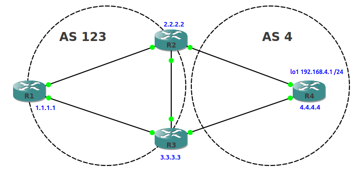
The previous post in this series looked at the exchange of routes between BGP peers, and this post takes this a step further by looking at two BGP attributes that can be modified to influence how a router decides which routes to place in it’s routing table – WEIGHT and LOCAL PREFERENCE

Here’s our example network and initial BGP configs:

BGP Basics - Modifying Attributes

R1#sh run | s router 
router bgp 123
 no synchronization
 bgp log-neighbor-changes
 neighbor 2.2.2.2 remote-as 123
 neighbor 2.2.2.2 update-source Loopback0
 neighbor 3.3.3.3 remote-as 123
 neighbor 3.3.3.3 update-source Loopback0
 no auto-summary

R2#sh run | s router
router bgp 123
 no synchronization
 bgp log-neighbor-changes
 neighbor 1.1.1.1 remote-as 123
 neighbor 1.1.1.1 update-source Loopback0
 neighbor 1.1.1.1 next-hop-self
 neighbor 3.3.3.3 remote-as 123
 neighbor 3.3.3.3 update-source Loopback0
 neighbor 4.4.4.4 remote-as 4
 neighbor 4.4.4.4 ebgp-multihop 2
 neighbor 4.4.4.4 update-source Loopback0
 no auto-summary

R3#sh run | s router
router bgp 123
 no synchronization
 bgp log-neighbor-changes
 network 192.168.3.0
 neighbor 1.1.1.1 remote-as 123
 neighbor 1.1.1.1 update-source Loopback0
 neighbor 1.1.1.1 next-hop-self
 neighbor 2.2.2.2 remote-as 123
 neighbor 2.2.2.2 update-source Loopback0
 neighbor 4.4.4.4 remote-as 4
 neighbor 4.4.4.4 ebgp-multihop 2
 neighbor 4.4.4.4 update-source Loopback0
 no auto-summary

R4#sh run | s router
router bgp 4
 no synchronization
 bgp log-neighbor-changes
 network 192.168.4.0
 neighbor 2.2.2.2 remote-as 123
 neighbor 2.2.2.2 ebgp-multihop 2
 neighbor 2.2.2.2 update-source Loopback0
 neighbor 3.3.3.3 remote-as 123
 neighbor 3.3.3.3 ebgp-multihop 2
 neighbor 3.3.3.3 update-source Loopback0
 no auto-summary

We can see that R1 has 2 valid paths to the 192.168.4.0/24 network and the best route (via R2) has been placed in it’s routing table:

R1#sh ip bgp
BGP table version is 4, local router ID is 1.1.1.1
Status codes: s suppressed, d damped, h history, * valid, > best, i - internal,
              r RIB-failure, S Stale
Origin codes: i - IGP, e - EGP, ? - incomplete

   Network          Next Hop            Metric LocPrf Weight Path
*>i192.168.4.0      2.2.2.2                  0    100      0 4 i
* i                 3.3.3.3                  0    100      0 4 i

R1#sh ip route bgp
B    192.168.4.0/24 [200/0] via 2.2.2.2, 00:05:48

WEIGHT

WEIGHT is an attribute local to the router it is configured on, and is set per neighbour. As we can see from R1’s BGP table above, the default value for WEIGHT is 0. In this example we’ll set R1’s WEIGHT attribute for R3 to 100 so that R3 becomes the preferred path to the 192.168.4.0/24 network:

R1(config)#router bgp 123               
R1(config-router)#neighbor 3.3.3.3 weight 100

Reset the peers to see the effect of this on R1’s BGP table:

R1#clear ip bgp *

R1#sh ip bgp      
BGP table version is 2, local router ID is 1.1.1.1
Status codes: s suppressed, d damped, h history, * valid, > best, i - internal,
              r RIB-failure, S Stale
Origin codes: i - IGP, e - EGP, ? - incomplete

   Network          Next Hop            Metric LocPrf Weight Path
*>i192.168.4.0      3.3.3.3                  0    100    100 4 i
* i                 2.2.2.2                  0    100      0 4 i

The Weight for R3 is now 100, so the best path is now via R3. R1 places this route in it’s routing table:

R1#sh ip route bgp
B    192.168.4.0/24 [200/0] via 3.3.3.3, 00:00:14

LOCAL PREFERENCE

This can be advertised from a router to other routers within same (local) AS, and has a value of 100 by default. In this example we’ll configure a local preference on R3 of 200, to achieve the same end result as before.

First we’ll remove the WEIGHT config from the first example:

R1(config)#router bgp 123
R1(config-router)#no neighbor 3.3.3.3 weight 100
R1(config-router)#do clear ip bgp * 

Next, we’ll configure R3 so it has a LOCAL PREFERENCE of 200:

R3(config)#router bgp 123                  
R3(config-router)#bgp default local-preference 200
R3(config-router)#do clear bgp *

Remember that this attribute is local to the AS (123 in this case) so to verify this we can check R1’s bgp and routing tables:

R1#sh ip bgp      
BGP table version is 9, local router ID is 1.1.1.1
Status codes: s suppressed, d damped, h history, * valid, > best, i - internal,
              r RIB-failure, S Stale
Origin codes: i - IGP, e - EGP, ? - incomplete

   Network          Next Hop            Metric LocPrf Weight Path
*>i192.168.4.0      3.3.3.3                  0    200      0 4 i

R1#sh ip route bgp
B    192.168.4.0/24 [200/0] via 3.3.3.3, 00:01:36

From the output above we can see that R1 now only has 1 valid and best path to 192.168.4.0/24, and it is via R3.

I hope this has been a useful explanation. Thanks for reading, and good luck with your CCNP studies!

Rich

Follow Rich on Twitter

BGP Basics – advertising networks into BGP

The first post in this BGP mini-series looked at setting up BGP peering between routers. Now we’ll take things a step further and actually exchange some routing information between those peers. Here’s the network:
bgp basics - exchanging routes

The basic BGP config on each router looks like this:

R1#sh run | s router
router bgp 1
 no synchronization
 bgp log-neighbor-changes
 neighbor 2.2.2.2 remote-as 23
 neighbor 2.2.2.2 ebgp-multihop 2
 neighbor 2.2.2.2 update-source Loopback0
 neighbor 3.3.3.3 remote-as 23
 neighbor 3.3.3.3 ebgp-multihop 2
 neighbor 3.3.3.3 update-source Loopback0
 no auto-summary

R2#sh run | s router
router bgp 23
 no synchronization
 bgp log-neighbor-changes
 neighbor 1.1.1.1 remote-as 1
 neighbor 1.1.1.1 ebgp-multihop 2
 neighbor 1.1.1.1 update-source Loopback0
 neighbor 3.3.3.3 remote-as 23
 neighbor 3.3.3.3 ebgp-multihop 2
 neighbor 3.3.3.3 update-source Loopback0
 no auto-summary

R3#sh run | s router
router bgp 23
 no synchronization
 bgp log-neighbor-changes
 neighbor 1.1.1.1 remote-as 1
 neighbor 1.1.1.1 ebgp-multihop 2
 neighbor 1.1.1.1 update-source Loopback0
 neighbor 2.2.2.2 remote-as 23
 neighbor 2.2.2.2 ebgp-multihop 2
 neighbor 2.2.2.2 update-source Loopback0
 no auto-summary

We’ve now got peering between all three routers, but no routes are being learned yet via BGP. So far only static and connected routes are shown in the routing tables and we can see this on R1:

R1#sh ip bgp neighbors | i BGP
BGP neighbor is 2.2.2.2,  remote AS 23 external link
  BGP version 4, remote router ID 2.2.2.2
  BGP state = Established, up for 05:17:02
  BGP table version 1, neighbor version 1/0
  External BGP neighbor may be up to 2 hops away.
BGP neighbor is 3.3.3.3,  remote AS 23 external link
  BGP version 4, remote router ID 3.3.3.3
  BGP state = Established, up for 05:16:57
  BGP table version 1, neighbor version 1/0
  External BGP neighbor may be up to 2 hops away.

R1#sh ip route
{output omitted}

Gateway of last resort is not set

     1.0.0.0/32 is subnetted, 1 subnets
C       1.1.1.1 is directly connected, Loopback0
     2.0.0.0/32 is subnetted, 1 subnets
S       2.2.2.2 [1/0] via 10.0.12.2
     3.0.0.0/32 is subnetted, 1 subnets
S       3.3.3.3 [1/0] via 10.0.13.3
     10.0.0.0/29 is subnetted, 2 subnets
C       10.0.12.0 is directly connected, FastEthernet0/0
C       10.0.13.0 is directly connected, FastEthernet1/0

There are two main methods of advertising routes into BGP – network statements and redistribution.

Network Statements

On R2 we will use a network statement to advertise the 192.168.2.0 /24 network into BGP (note that bgp network statements use subnet masks rather than wildcard masks):

R2(config)#router bgp 23
R2(config-router)#network 192.168.2.0 mask 255.255.255.0

If we check R1’s BGP table we see that it has learned of 192.168.2.0/24 route, also that the best route is via R2, and that the path is through AS23:

R1#sh ip bgp             
BGP table version is 36, local router ID is 1.1.1.1
Status codes: s suppressed, d damped, h history, * valid, > best, i - internal,
              r RIB-failure, S Stale
Origin codes: i - IGP, e - EGP, ? - incomplete

   Network          Next Hop            Metric LocPrf Weight Path
*  192.168.2.0      3.3.3.3                                0 23 i
*>                  2.2.2.2                  0             0 23 i

The best route is now also in R1’s routing table (note the administrative distance of 20 for external BGP):

R1#sh ip route bgp
B    192.168.2.0/24 [20/0] via 2.2.2.2, 00:25:55

Redistribution

On R3 we will redistribute connected networks so that we advertise the 192.168.3.0 /24 network into BGP:

R3(config)#router bgp 23         
R3(config-router)#redistribute connected

This works but is a little clumsy. We can now see the 192.168.3.0 /24 network in R1’s routing table, but we also see the 10.0.23.0 /29 transit network between R2 and R3:

R1#show ip route bgp
     10.0.0.0/29 is subnetted, 3 subnets
B       10.0.23.0 [20/0] via 3.3.3.3, 00:01:22
B    192.168.2.0/24 [20/0] via 2.2.2.2, 00:20:27
B    192.168.3.0/24 [20/0] via 3.3.3.3, 00:01:22

Plus we also get some RIB failure messages relating to R3’s other connected networks:

R1#sh ip bgp                                                       
BGP table version is 8, local router ID is 1.1.1.1
Status codes: s suppressed, d damped, h history, * valid, > best, i - internal,
              r RIB-failure, S Stale
Origin codes: i - IGP, e - EGP, ? - incomplete

   Network          Next Hop            Metric LocPrf Weight Path
r  3.3.3.3/32       2.2.2.2                                0 23 ?
r>                  3.3.3.3                  0             0 23 ?
r  10.0.13.0/29     2.2.2.2                                0 23 ?
r>                  3.3.3.3                  0             0 23 ?
*  10.0.23.0/29     2.2.2.2                                0 23 ?
*>                  3.3.3.3                  0             0 23 ?
*  192.168.2.0      3.3.3.3                                0 23 i
*>                  2.2.2.2                  0             0 23 i
*  192.168.3.0      2.2.2.2                                0 23 ?
*>                  3.3.3.3                  0             0 23 ?

This is because R1 already has a static route to 3.3.3.3/32 and is directly connected to 10.0.13.0/29.

To tidy this up we’ll filter routes using a route map that references an access list to match only the 192.168.3.0/24 network:

R3(config)#route-map R3RouteMap permit 10
R3(config-route-map)#match ip address 10

R3(config)#access-list 10 permit 192.168.3.0 0.0.0.255

R3(config)#router bgp 23 
R3(config-router)#redistribute connected route-map R3RouteMap

Now R1 only learns the route to 192.168.3.0/24 from R3, as the route map is preventing the other networks from being advertised:

R1#sh ip bgp
BGP table version is 17, local router ID is 1.1.1.1
Status codes: s suppressed, d damped, h history, * valid, > best, i - internal,
              r RIB-failure, S Stale
Origin codes: i - IGP, e - EGP, ? - incomplete

   Network          Next Hop            Metric LocPrf Weight Path
*  192.168.2.0      3.3.3.3                                0 23 i
*>                  2.2.2.2                  0             0 23 i
*  192.168.3.0      2.2.2.2                                0 23 ?
*>                  3.3.3.3                  0             0 23 ?
 

R1#sh ip route bgp
B    192.168.2.0/24 [20/0] via 2.2.2.2, 02:20:54
B    192.168.3.0/24 [20/0] via 3.3.3.3, 02:16:40

As well being less clumsy, this is much more like a real-world scenario where an ISP would be filtering the routes it advertises to a customer or vice versa.

I hope this has been a useful explanation. The next post in this series looks at modifying BGP attributes to inlfuence route selection.

Thanks for reading, and good luck with your CCNP studies!

Rich

Follow Rich on Twitter

BGP Basics – iBGP and eBGP peering

This is the first post in a mini-series on BGP basics, and looks at setting up internal and external BGP neighbours using loopback interfaces. The advantage loopbacks have over physical interfaces is that they are always up and reachable.

iBGP configuration:

ibgp peering

The routers must be able to reach each others loopback IP’s and we don’t have any dynamic routing protocols running yet, so we add static routes:

R1#sh run | i ip route
ip route 2.2.2.2 255.255.255.255 10.0.0.2

R2#sh run | i ip route 
ip route 1.1.1.1 255.255.255.255 10.0.0.1
R2#ping 1.1.1.1

Type escape sequence to abort.
Sending 5, 100-byte ICMP Echos to 1.1.1.1, timeout is 2 seconds:
!!!!!
Success rate is 100 percent (5/5), round-trip min/avg/max = 16/20/24 ms

Next, configure the BGP process on each router to use the same AS number, then specify the neighbour, and tell BGP to establish the TCP connection (BGP uses tcp/179) using the loopback 0 interface:

R1#sh run | s router 
router bgp 100
 no synchronization
 bgp log-neighbor-changes
 neighbor 2.2.2.2 remote-as 100
 neighbor 2.2.2.2 update-source Loopback0
 no auto-summary

R2#sh run | s router
router bgp 100
 no synchronization
 bgp log-neighbor-changes
 neighbor 1.1.1.1 remote-as 100
 neighbor 1.1.1.1 update-source Loopback0
 no auto-summary

Verify the configuration:

R1#show ip bgp neighbors | include BGP
BGP neighbor is 2.2.2.2,  remote AS 100, internal link
  BGP version 4, remote router ID 2.2.2.2
  BGP state = Established, up for 00:04:10
  BGP table version 1, neighbor version 1/0

R1#show ip bgp summary
BGP router identifier 1.1.1.1, local AS number 100
BGP table version is 1, main routing table version 1

Neighbor        V    AS MsgRcvd MsgSent   TblVer  InQ OutQ Up/Down  State/PfxRcd
2.2.2.2         4   100       9       9        1    0    0 00:05:21        0

eBGP configuration:

ebgp peering

First, configure the BGP process on each router under the local AS number. Then configure the neighbour with the remote AS number, using loopbacks to connect:

R1#sh run | s router            
router bgp 111
 no synchronization
 bgp log-neighbor-changes
 neighbor 2.2.2.2 remote-as 222
 neighbor 2.2.2.2 update-source Loopback0
 no auto-summary

R2#sh run | s router
router bgp 222
 no synchronization
 bgp log-neighbor-changesre 
 neighbor 1.1.1.1 remote-as 111
 neighbor 1.1.1.1 update-source Loopback0
 no auto-summary

At this point we still don’t have established neighbours:

R2#sh ip bgp summary 
BGP router identifier 2.2.2.2, local AS number 222
BGP table version is 1, main routing table version 1

Neighbor        V    AS MsgRcvd MsgSent   TblVer  InQ OutQ Up/Down  State/PfxRcd
1.1.1.1         4   111       0       0        0    0    0 never    Idle
 
R2#sh ip bgp neighbors | i BGP
BGP neighbor is 1.1.1.1,  remote AS 111, external link
  BGP version 4, remote router ID 0.0.0.0
  BGP state = Idle
  BGP table version 1, neighbor version 0/0
  External BGP neighbor not directly connected.

The reason for this is that eBGP neighbours using an interface that is not directly connected need an extra command that sets the TTL value for the packet to a value that allows it to reach the loopback interface (in this case 2 hops):

R1(config)#router bgp 111
R1(config-router)#neighbor 2.2.2.2 ebgp-multihop 2

R2(config)#router bgp 222
R2(config-router)#neighbor 1.1.1.1 ebgp-multihop 2

Verify the configuration:

R1#sh ip bgp summary 
BGP router identifier 1.1.1.1, local AS number 111
BGP table version is 1, main routing table version 1

Neighbor        V    AS MsgRcvd MsgSent   TblVer  InQ OutQ Up/Down  State/PfxRcd
2.2.2.2         4   222       8       8        1    0    0 00:04:10        0

R1#sh ip bgp neighbors | i BGP
BGP neighbor is 2.2.2.2,  remote AS 222, external link
  BGP version 4, remote router ID 2.2.2.2
  BGP state = Established, up for 00:04:46
  BGP table version 1, neighbor version 1/0
  External BGP neighbor may be up to 2 hops away.

I hope this has been a useful explanation. The next post in this series looks at advertising networks into BGP.

Thanks for reading, and good luck with your CCNP studies!

Rich

Follow Rich on Twitter

CCNP ROUTE Study – OSPF Virtual Links

One of the golden rules of OSPF is that all areas must be connected to the backbone area 0, however sometimes this is not physically possible, and this is where Virtual Links come in. A virtual link is created through another area that is connected to area 0.

To explain this, here is our network:

OSPF VIrtual Links

In our network the remote branch router R3 has interfaces in area 23 and area 100, but not area 0. Because area 100 is not connected to the backbone area 0, routes to the branch LAN prefix 10.0.0.0/24 will not be learned by R1.

We can see that R1 has learnt of the Inter Area route to the 192.168.50.0/30 prefix in area 23, but has no knowledge of anything from area 100.

To prove this, let’s look at R1’s routing table:

R1#show ip route  
Codes: C - connected, S - static, R - RIP, M - mobile, B - BGP
       D - EIGRP, EX - EIGRP external, O - OSPF, IA - OSPF inter area 
       N1 - OSPF NSSA external type 1, N2 - OSPF NSSA external type 2
       E1 - OSPF external type 1, E2 - OSPF external type 2
       i - IS-IS, su - IS-IS summary, L1 - IS-IS level-1, L2 - IS-IS level-2
       ia - IS-IS inter area, * - candidate default, U - per-user static route
       o - ODR, P - periodic downloaded static route

Gateway of last resort is not set

     192.168.20.0/30 is subnetted, 1 subnets
C       192.168.20.0 is directly connected, FastEthernet0/0
     192.168.50.0/30 is subnetted, 1 subnets
O IA    192.168.50.0 [110/2] via 192.168.20.2, 02:08:32, FastEthernet0/0

To fix this up we create a Virtual Link through area 23 (between R2 and R3) to the backbone area 0 from area 100. Virtual Links are configured referencing the Router ID’s at each end of the link:

R2(config)#router ospf 1
R2(config-router)#area 23 virtual-link 3.3.3.3
R3(config)#router ospf 1
R3(config-router)#area 23 virtual-link 2.2.2.2

Both routers will now indicate that a new link has come up:

R2#
*Mar  1 03:03:24.255: %OSPF-5-ADJCHG: Process 1, Nbr 3.3.3.3 on OSPF_VL1 from LOADING to FULL, Loading Done

The command show ip ospf virtual-links will also confirm the link is up and that area 23 is being used as the transit area:

R2#show ip ospf virtual-links 
Virtual Link OSPF_VL1 to router 3.3.3.3 is up
  Run as demand circuit
  DoNotAge LSA allowed.
  Transit area 23, via interface FastEthernet0/1, Cost of using 1
  Transmit Delay is 1 sec, State POINT_TO_POINT,
  Timer intervals configured, Hello 10, Dead 40, Wait 40, Retransmit 5
    Hello due in 00:00:07
    Adjacency State FULL (Hello suppressed)
    Index 2/3, retransmission queue length 0, number of retransmission 1
    First 0x0(0)/0x0(0) Next 0x0(0)/0x0(0)
    Last retransmission scan length is 1, maximum is 1
    Last retransmission scan time is 0 msec, maximum is 0 msec

So now area 100 has a virtual link to the backbone area, we should see the remote branch LAN prefix in the routing table of R1 as an Inter Area route:

R1#sh ip route              
Codes: C - connected, S - static, R - RIP, M - mobile, B - BGP
       D - EIGRP, EX - EIGRP external, O - OSPF, IA - OSPF inter area 
       N1 - OSPF NSSA external type 1, N2 - OSPF NSSA external type 2
       E1 - OSPF external type 1, E2 - OSPF external type 2
       i - IS-IS, su - IS-IS summary, L1 - IS-IS level-1, L2 - IS-IS level-2
       ia - IS-IS inter area, * - candidate default, U - per-user static route
       o - ODR, P - periodic downloaded static route

Gateway of last resort is not set

     192.168.20.0/30 is subnetted, 1 subnets
C       192.168.20.0 is directly connected, FastEthernet0/0
     10.0.0.0/24 is subnetted, 1 subnets
O IA    10.0.0.0 [110/3] via 192.168.20.2, 00:04:02, FastEthernet0/0
     192.168.50.0/30 is subnetted, 1 subnets
O IA    192.168.50.0 [110/2] via 192.168.20.2, 00:04:02, FastEthernet0/0

I hope this has been a useful explanation.  Thanks for reading, and good luck with your CCNP studies!

Rich

Follow Rich on Twitter

CCNP ROUTE Study – OSPF DR/BDR Elections (and how to rig them….)

OSPF DR:BDR Election

When multiple OSPF routers are connected to a multi-access medium such as Ethernet, a Designated Router (DR) and a Backup Designated Router (BDR) are elected. DR’s reduce network traffic as only they maintain the complete ospf database and then send updates to the other routers on the shared network segment.

The other routers become ‘slaves’ to the ‘master’ DR. ‘Slave’ routers only become FULL neighbours with the DR and BDR, remaining at the 2-WAY state with the other non-DR/BDR routers. The BDR takes over should the DR fail, and then there is another election for the role of BDR.

The router with the highest priority on the data link wins the election, but by default priorities are set to zero, so we end up with a tie. In this case the router with the highest Router ID will win.

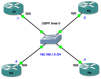
Here’s our network to illustrate this:

OSPF DR:BDR Election

In our network with default settings, assuming all OSPF router processes start at the same time, R4 and R3 win the election for DR and BDR respectively because they have the highest Router ID’s on the segment.

There are a couple of good commands we can use to verify this, the first one being show ip ospf neighbor. From the output below, we can see that R4 has FULL relationships with all of the other routers and that R3 is the BDR:

R4>show ip ospf neighbor 

Neighbor ID     Pri   State           Dead Time   Address         Interface
192.168.1.1       1   FULL/DROTHER    00:00:34    192.168.1.1     FastEthernet0/0
192.168.1.2       1   FULL/DROTHER    00:00:32    192.168.1.2     FastEthernet0/0
192.168.1.3       1   FULL/BDR        00:00:32    192.168.1.3     FastEthernet0/0

The show ip ospf interface, command gives us more detail about R4’s relationships with the other routers on the segment, including the fact that it is the DR:

R4>show ip ospf interface 
FastEthernet0/0 is up, line protocol is up 
  Internet Address 192.168.1.4/24, Area 0 
  Process ID 1, Router ID 192.168.1.4, Network Type BROADCAST, Cost: 1
  Transmit Delay is 1 sec, State DR, Priority 1 
  Designated Router (ID) 192.168.1.4, Interface address 192.168.1.4
  Backup Designated router (ID) 192.168.1.3, Interface address 192.168.1.3
  Timer intervals configured, Hello 10, Dead 40, Wait 40, Retransmit 5
    oob-resync timeout 40
    Hello due in 00:00:01
  Index 1/1, flood queue length 0
  Next 0x0(0)/0x0(0)
  Last flood scan length is 0, maximum is 1
  Last flood scan time is 0 msec, maximum is 0 msec
  Neighbor Count is 3, Adjacent neighbor count is 3 
    Adjacent with neighbor 192.168.1.1
    Adjacent with neighbor 192.168.1.2
    Adjacent with neighbor 192.168.1.3  (Backup Designated Router)
  Suppress hello for 0 neighbor(s)

Now, suppose we wanted to control which routers are going to be our DR and BDR, we can do this by giving their interfaces higher priorities. In our example, we’ll make R1 the DR and R2 the BDR:

R1(config)#interface fa0/0
R1(config-if)#ip ospf priority 100
R2(config)#interface fa0/0
R2(config-if)#ip ospf priority 50

Now, if we clear the ospf process on each router with the clear ip ospf process command, we can verify that our config has worked. Firstly let’s check R4’s view of it’s neighbours:

R4#show ip ospf neighbor 

Neighbor ID     Pri   State           Dead Time   Address         Interface
192.168.1.1     100   FULL/DR         00:00:37    192.168.1.1     FastEthernet0/0
192.168.1.2      50   FULL/BDR        00:00:38    192.168.1.2     FastEthernet0/0
192.168.1.3       1   2WAY/DROTHER    00:00:39    192.168.1.3     FastEthernet0/0

Lets check R1’s view of things from an interface point of view:

R1#show ip ospf interface
FastEthernet0/0 is up, line protocol is up 
  Internet Address 192.168.1.1/24, Area 0 
  Process ID 1, Router ID 192.168.1.1, Network Type BROADCAST, Cost: 1
  Transmit Delay is 1 sec, State DR, Priority 100 
  Designated Router (ID) 192.168.1.1, Interface address 192.168.1.1
  Backup Designated router (ID) 192.168.1.2, Interface address 192.168.1.2
  Timer intervals configured, Hello 10, Dead 40, Wait 40, Retransmit 5
    oob-resync timeout 40
    Hello due in 00:00:05
  Index 1/1, flood queue length 0
  Next 0x0(0)/0x0(0)
  Last flood scan length is 1, maximum is 1
  Last flood scan time is 0 msec, maximum is 0 msec
  Neighbor Count is 3, Adjacent neighbor count is 3 
    Adjacent with neighbor 192.168.1.2  (Backup Designated Router)
    Adjacent with neighbor 192.168.1.3
    Adjacent with neighbor 192.168.1.4
  Suppress hello for 0 neighbor(s)

And finally, let’s get a detailed picture of R1’s ospf neighbour relationships, with the show ip ospf neighbor detail command:

R1#show ip ospf neighbor detail 
 Neighbor 192.168.1.2, interface address 192.168.1.2
    In the area 0 via interface FastEthernet0/0 
    Neighbor priority is 50, State is FULL, 6 state changes
    DR is 192.168.1.1 BDR is 192.168.1.2
    Options is 0x52
    LLS Options is 0x1 (LR)
    Dead timer due in 00:00:39
    Neighbor is up for 00:15:50
    Index 1/1, retransmission queue length 0, number of retransmission 1
    First 0x0(0)/0x0(0) Next 0x0(0)/0x0(0)
    Last retransmission scan length is 1, maximum is 1
    Last retransmission scan time is 0 msec, maximum is 0 msec
 Neighbor 192.168.1.3, interface address 192.168.1.3
    In the area 0 via interface FastEthernet0/0 
    Neighbor priority is 1, State is FULL, 6 state changes
    DR is 192.168.1.1 BDR is 192.168.1.2
    Options is 0x52
    LLS Options is 0x1 (LR)
    Dead timer due in 00:00:30
    Neighbor is up for 00:15:49
    Index 3/3, retransmission queue length 0, number of retransmission 1
    First 0x0(0)/0x0(0) Next 0x0(0)/0x0(0)
    Last retransmission scan length is 1, maximum is 1
    Last retransmission scan time is 0 msec, maximum is 0 msec
 Neighbor 192.168.1.4, interface address 192.168.1.4
    In the area 0 via interface FastEthernet0/0 
    Neighbor priority is 1, State is FULL, 6 state changes
    DR is 192.168.1.1 BDR is 192.168.1.2
    Options is 0x52
    LLS Options is 0x1 (LR)
    Dead timer due in 00:00:37
    Neighbor is up for 00:15:52
    Index 2/2, retransmission queue length 0, number of retransmission 1
    First 0x0(0)/0x0(0) Next 0x0(0)/0x0(0)
    Last retransmission scan length is 1, maximum is 1
    Last retransmission scan time is 0 msec, maximum is 0 msec

I hope this has been a useful explanation.  Thanks for reading, and good luck with your CCNP studies!

Rich

Follow Rich on Twitter