Monthly Archives: January 2014

CCNP ROUTE Study – OSPF Virtual Links

One of the golden rules of OSPF is that all areas must be connected to the backbone area 0, however sometimes this is not physically possible, and this is where Virtual Links come in. A virtual link is created through another area that is connected to area 0.

To explain this, here is our network:

OSPF VIrtual Links

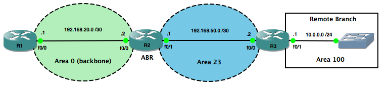
In our network the remote branch router R3 has interfaces in area 23 and area 100, but not area 0. Because area 100 is not connected to the backbone area 0, routes to the branch LAN prefix 10.0.0.0/24 will not be learned by R1.

We can see that R1 has learnt of the Inter Area route to the 192.168.50.0/30 prefix in area 23, but has no knowledge of anything from area 100.

To prove this, let’s look at R1’s routing table:

R1#show ip route  
Codes: C - connected, S - static, R - RIP, M - mobile, B - BGP
       D - EIGRP, EX - EIGRP external, O - OSPF, IA - OSPF inter area 
       N1 - OSPF NSSA external type 1, N2 - OSPF NSSA external type 2
       E1 - OSPF external type 1, E2 - OSPF external type 2
       i - IS-IS, su - IS-IS summary, L1 - IS-IS level-1, L2 - IS-IS level-2
       ia - IS-IS inter area, * - candidate default, U - per-user static route
       o - ODR, P - periodic downloaded static route

Gateway of last resort is not set

     192.168.20.0/30 is subnetted, 1 subnets
C       192.168.20.0 is directly connected, FastEthernet0/0
     192.168.50.0/30 is subnetted, 1 subnets
O IA    192.168.50.0 [110/2] via 192.168.20.2, 02:08:32, FastEthernet0/0

To fix this up we create a Virtual Link through area 23 (between R2 and R3) to the backbone area 0 from area 100. Virtual Links are configured referencing the Router ID’s at each end of the link:

R2(config)#router ospf 1
R2(config-router)#area 23 virtual-link 3.3.3.3
R3(config)#router ospf 1
R3(config-router)#area 23 virtual-link 2.2.2.2

Both routers will now indicate that a new link has come up:

R2#
*Mar  1 03:03:24.255: %OSPF-5-ADJCHG: Process 1, Nbr 3.3.3.3 on OSPF_VL1 from LOADING to FULL, Loading Done

The command show ip ospf virtual-links will also confirm the link is up and that area 23 is being used as the transit area:

R2#show ip ospf virtual-links 
Virtual Link OSPF_VL1 to router 3.3.3.3 is up
  Run as demand circuit
  DoNotAge LSA allowed.
  Transit area 23, via interface FastEthernet0/1, Cost of using 1
  Transmit Delay is 1 sec, State POINT_TO_POINT,
  Timer intervals configured, Hello 10, Dead 40, Wait 40, Retransmit 5
    Hello due in 00:00:07
    Adjacency State FULL (Hello suppressed)
    Index 2/3, retransmission queue length 0, number of retransmission 1
    First 0x0(0)/0x0(0) Next 0x0(0)/0x0(0)
    Last retransmission scan length is 1, maximum is 1
    Last retransmission scan time is 0 msec, maximum is 0 msec

So now area 100 has a virtual link to the backbone area, we should see the remote branch LAN prefix in the routing table of R1 as an Inter Area route:

R1#sh ip route              
Codes: C - connected, S - static, R - RIP, M - mobile, B - BGP
       D - EIGRP, EX - EIGRP external, O - OSPF, IA - OSPF inter area 
       N1 - OSPF NSSA external type 1, N2 - OSPF NSSA external type 2
       E1 - OSPF external type 1, E2 - OSPF external type 2
       i - IS-IS, su - IS-IS summary, L1 - IS-IS level-1, L2 - IS-IS level-2
       ia - IS-IS inter area, * - candidate default, U - per-user static route
       o - ODR, P - periodic downloaded static route

Gateway of last resort is not set

     192.168.20.0/30 is subnetted, 1 subnets
C       192.168.20.0 is directly connected, FastEthernet0/0
     10.0.0.0/24 is subnetted, 1 subnets
O IA    10.0.0.0 [110/3] via 192.168.20.2, 00:04:02, FastEthernet0/0
     192.168.50.0/30 is subnetted, 1 subnets
O IA    192.168.50.0 [110/2] via 192.168.20.2, 00:04:02, FastEthernet0/0

I hope this has been a useful explanation.  Thanks for reading, and good luck with your CCNP studies!

Rich

Follow Rich on Twitter

CCNP ROUTE Study – OSPF DR/BDR Elections (and how to rig them….)

OSPF DR:BDR Election

When multiple OSPF routers are connected to a multi-access medium such as Ethernet, a Designated Router (DR) and a Backup Designated Router (BDR) are elected. DR’s reduce network traffic as only they maintain the complete ospf database and then send updates to the other routers on the shared network segment.

The other routers become ‘slaves’ to the ‘master’ DR. ‘Slave’ routers only become FULL neighbours with the DR and BDR, remaining at the 2-WAY state with the other non-DR/BDR routers. The BDR takes over should the DR fail, and then there is another election for the role of BDR.

The router with the highest priority on the data link wins the election, but by default priorities are set to zero, so we end up with a tie. In this case the router with the highest Router ID will win.

Here’s our network to illustrate this:

OSPF DR:BDR Election

In our network with default settings, assuming all OSPF router processes start at the same time, R4 and R3 win the election for DR and BDR respectively because they have the highest Router ID’s on the segment.

There are a couple of good commands we can use to verify this, the first one being show ip ospf neighbor. From the output below, we can see that R4 has FULL relationships with all of the other routers and that R3 is the BDR:

R4>show ip ospf neighbor 

Neighbor ID     Pri   State           Dead Time   Address         Interface
192.168.1.1       1   FULL/DROTHER    00:00:34    192.168.1.1     FastEthernet0/0
192.168.1.2       1   FULL/DROTHER    00:00:32    192.168.1.2     FastEthernet0/0
192.168.1.3       1   FULL/BDR        00:00:32    192.168.1.3     FastEthernet0/0

The show ip ospf interface, command gives us more detail about R4’s relationships with the other routers on the segment, including the fact that it is the DR:

R4>show ip ospf interface 
FastEthernet0/0 is up, line protocol is up 
  Internet Address 192.168.1.4/24, Area 0 
  Process ID 1, Router ID 192.168.1.4, Network Type BROADCAST, Cost: 1
  Transmit Delay is 1 sec, State DR, Priority 1 
  Designated Router (ID) 192.168.1.4, Interface address 192.168.1.4
  Backup Designated router (ID) 192.168.1.3, Interface address 192.168.1.3
  Timer intervals configured, Hello 10, Dead 40, Wait 40, Retransmit 5
    oob-resync timeout 40
    Hello due in 00:00:01
  Index 1/1, flood queue length 0
  Next 0x0(0)/0x0(0)
  Last flood scan length is 0, maximum is 1
  Last flood scan time is 0 msec, maximum is 0 msec
  Neighbor Count is 3, Adjacent neighbor count is 3 
    Adjacent with neighbor 192.168.1.1
    Adjacent with neighbor 192.168.1.2
    Adjacent with neighbor 192.168.1.3  (Backup Designated Router)
  Suppress hello for 0 neighbor(s)

Now, suppose we wanted to control which routers are going to be our DR and BDR, we can do this by giving their interfaces higher priorities. In our example, we’ll make R1 the DR and R2 the BDR:

R1(config)#interface fa0/0
R1(config-if)#ip ospf priority 100
R2(config)#interface fa0/0
R2(config-if)#ip ospf priority 50

Now, if we clear the ospf process on each router with the clear ip ospf process command, we can verify that our config has worked. Firstly let’s check R4’s view of it’s neighbours:

R4#show ip ospf neighbor 

Neighbor ID     Pri   State           Dead Time   Address         Interface
192.168.1.1     100   FULL/DR         00:00:37    192.168.1.1     FastEthernet0/0
192.168.1.2      50   FULL/BDR        00:00:38    192.168.1.2     FastEthernet0/0
192.168.1.3       1   2WAY/DROTHER    00:00:39    192.168.1.3     FastEthernet0/0

Lets check R1’s view of things from an interface point of view:

R1#show ip ospf interface
FastEthernet0/0 is up, line protocol is up 
  Internet Address 192.168.1.1/24, Area 0 
  Process ID 1, Router ID 192.168.1.1, Network Type BROADCAST, Cost: 1
  Transmit Delay is 1 sec, State DR, Priority 100 
  Designated Router (ID) 192.168.1.1, Interface address 192.168.1.1
  Backup Designated router (ID) 192.168.1.2, Interface address 192.168.1.2
  Timer intervals configured, Hello 10, Dead 40, Wait 40, Retransmit 5
    oob-resync timeout 40
    Hello due in 00:00:05
  Index 1/1, flood queue length 0
  Next 0x0(0)/0x0(0)
  Last flood scan length is 1, maximum is 1
  Last flood scan time is 0 msec, maximum is 0 msec
  Neighbor Count is 3, Adjacent neighbor count is 3 
    Adjacent with neighbor 192.168.1.2  (Backup Designated Router)
    Adjacent with neighbor 192.168.1.3
    Adjacent with neighbor 192.168.1.4
  Suppress hello for 0 neighbor(s)

And finally, let’s get a detailed picture of R1’s ospf neighbour relationships, with the show ip ospf neighbor detail command:

R1#show ip ospf neighbor detail 
 Neighbor 192.168.1.2, interface address 192.168.1.2
    In the area 0 via interface FastEthernet0/0 
    Neighbor priority is 50, State is FULL, 6 state changes
    DR is 192.168.1.1 BDR is 192.168.1.2
    Options is 0x52
    LLS Options is 0x1 (LR)
    Dead timer due in 00:00:39
    Neighbor is up for 00:15:50
    Index 1/1, retransmission queue length 0, number of retransmission 1
    First 0x0(0)/0x0(0) Next 0x0(0)/0x0(0)
    Last retransmission scan length is 1, maximum is 1
    Last retransmission scan time is 0 msec, maximum is 0 msec
 Neighbor 192.168.1.3, interface address 192.168.1.3
    In the area 0 via interface FastEthernet0/0 
    Neighbor priority is 1, State is FULL, 6 state changes
    DR is 192.168.1.1 BDR is 192.168.1.2
    Options is 0x52
    LLS Options is 0x1 (LR)
    Dead timer due in 00:00:30
    Neighbor is up for 00:15:49
    Index 3/3, retransmission queue length 0, number of retransmission 1
    First 0x0(0)/0x0(0) Next 0x0(0)/0x0(0)
    Last retransmission scan length is 1, maximum is 1
    Last retransmission scan time is 0 msec, maximum is 0 msec
 Neighbor 192.168.1.4, interface address 192.168.1.4
    In the area 0 via interface FastEthernet0/0 
    Neighbor priority is 1, State is FULL, 6 state changes
    DR is 192.168.1.1 BDR is 192.168.1.2
    Options is 0x52
    LLS Options is 0x1 (LR)
    Dead timer due in 00:00:37
    Neighbor is up for 00:15:52
    Index 2/2, retransmission queue length 0, number of retransmission 1
    First 0x0(0)/0x0(0) Next 0x0(0)/0x0(0)
    Last retransmission scan length is 1, maximum is 1
    Last retransmission scan time is 0 msec, maximum is 0 msec

I hope this has been a useful explanation.  Thanks for reading, and good luck with your CCNP studies!

Rich

Follow Rich on Twitter